Product Description
We also have a large number of edge banding machine and engraving machine accessories, you need accessories we have, and the price is right, if you need please contact us, thank you
/* January 22, 2571 19:08:37 */!function(){function s(e,r){var a,o={};try{e&&e.split(“,”).forEach(function(e,t){e&&(a=e.match(/(.*?):(.*)$/))&&1
| After-sales Service: | Mailbox |
|---|---|
| Warranty: | 1 Year |
| Material: | High-Strength Material |
| Customized: | Non-Customized |
| Condition: | New |
| Certification: | There Is No |
How do cardan shafts ensure efficient power transfer while maintaining balance?
Cardan shafts are designed to ensure efficient power transfer while maintaining balance between the driving and driven components. They employ various mechanisms and features that contribute to both aspects. Let’s explore how cardan shafts achieve efficient power transfer and balance:
1. Universal Joints:
– Cardan shafts utilize universal joints, also known as U-joints, to transmit torque from the driving component to the driven component. Universal joints consist of a cross-shaped yoke with needle bearings at each end. These needle bearings allow the joints to pivot and accommodate angular misalignment between the driving and driven components. By allowing for flexibility in movement, universal joints ensure efficient power transfer even when the components are not perfectly aligned, minimizing energy losses and maintaining balance.
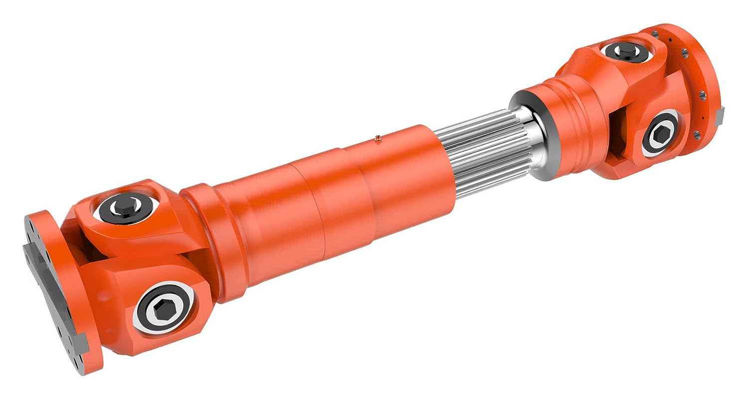
2. Misalignment Compensation:
– Cardan shafts are designed to compensate for misalignment between the driving and driven components. The universal joints, along with slip yokes and telescopic sections, allow the shaft to adjust its length and accommodate variations in alignment. This misalignment compensation capability ensures that the cardan shaft can transmit power smoothly and efficiently, reducing stress on the components and maintaining balance during operation.
3. Balanced Design:
– Cardan shafts are engineered with a balanced design to minimize vibration and maintain smooth operation. The shaft tubes are typically symmetrically constructed, and the universal joints are positioned to distribute the mass evenly. This balanced design helps to reduce vibration and minimize the occurrence of unbalanced forces that can negatively impact power transfer and overall system performance. By maintaining balance, cardan shafts contribute to efficient power transmission and improve the lifespan of the components involved.
4. High-Quality Materials and Manufacturing:
– The materials used in the construction of cardan shafts, such as steel or aluminum alloy, are carefully selected for their strength, durability, and ability to maintain balance. High-quality materials ensure that the shafts can withstand the torque and operational stresses without deformation or failure, promoting efficient power transfer. Additionally, precise manufacturing processes and quality control measures are employed to ensure that the cardan shafts are accurately balanced during production, further enhancing their efficiency and balance.
5. Regular Maintenance and Inspection:
– To ensure continued efficient power transfer and balance, regular maintenance and inspection of cardan shafts are essential. This includes periodic lubrication of the universal joints, checking for wear or damage, and addressing any misalignment issues. Regular maintenance helps to preserve the balance of the shaft and ensures optimal performance and longevity.
Overall, cardan shafts ensure efficient power transfer while maintaining balance through the use of universal joints for torque transmission, misalignment compensation mechanisms, balanced design, high-quality materials, and regular maintenance. By incorporating these features, cardan shafts contribute to the smooth operation, reliability, and longevity of various applications in automotive, industrial, and other sectors that rely on efficient power transmission.

How do cardan shafts handle variations in load, speed, and misalignment during operation?
Cardan shafts are designed to handle variations in load, speed, and misalignment during operation. They incorporate specific features and mechanisms to accommodate these factors and ensure efficient power transmission. Let’s explore how cardan shafts handle these variations:
1. Load Variation:
– Cardan shafts are designed to transmit torque and handle variations in load. The torque capacity of the shaft is determined based on the application’s requirements, and the shaft is manufactured using materials and dimensions that can withstand the specified loads. The design and construction of the shaft, including the selection of universal joints and slip yokes, are optimized to handle the anticipated loads. By choosing appropriate material strengths and dimensions, cardan shafts can effectively transmit varying loads without failure or excessive deflection.
2. Speed Variation:
– Cardan shafts can accommodate variations in rotational speed between the driving and driven components. The universal joints, which connect the shaft’s segments, allow for angular movement, thereby compensating for speed differences. The design of the universal joints and the use of needle bearings or roller bearings enable smooth rotation and efficient power transmission even at varying speeds. However, it’s important to note that excessively high speeds can introduce additional challenges such as increased vibration and wear, which may require additional measures such as balancing and lubrication.
3. Misalignment Compensation:
– Cardan shafts are specifically designed to handle misalignment between the driving and driven components. They can accommodate angular misalignment, parallel offset, and axial displacement to a certain extent. The universal joints in the shaft assembly allow for flexibility and articulation, enabling the shaft to transmit torque even when the components are not perfectly aligned. The design of the universal joints, along with their bearing arrangements and seals, allows for smooth rotation and compensation of misalignment. Manufacturers specify the maximum allowable misalignment angles and displacements for cardan shafts, and exceeding these limits can lead to increased wear, vibration, and reduced efficiency.
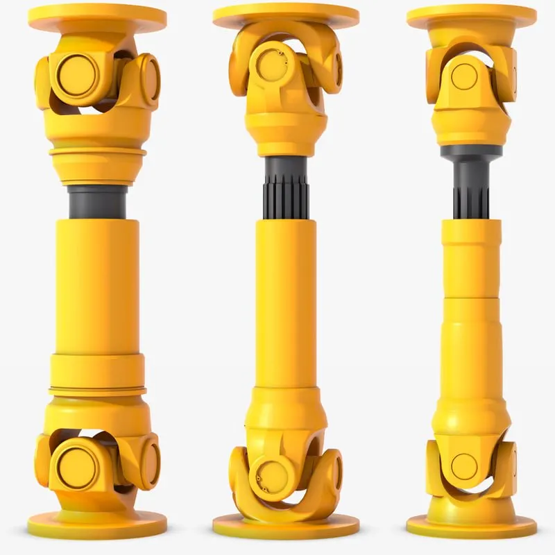
4. Telescopic Design:
– Cardan shafts often feature a telescopic design, which allows for axial movement and adjustment to accommodate variations in distance between the driving and driven components. This telescopic design enables the shaft to handle changes in length during operation, such as when the vehicle or equipment undergoes suspension movement or when the drivetrain components experience positional changes. The telescopic mechanism ensures that the shaft remains properly connected and engaged, maintaining power transmission efficiency even when there are fluctuations in distance or position.
5. Regular Maintenance:
– To ensure optimal performance and longevity, cardan shafts require regular maintenance. This includes inspections, lubrication of universal joints and slip yokes, and monitoring for wear or damage. Regular maintenance helps identify and address any issues related to load, speed, or misalignment variations, ensuring that the shaft continues to function effectively under changing operating conditions.
Overall, cardan shafts handle variations in load, speed, and misalignment through their design features such as universal joints, telescopic design, and flexibility. By incorporating these elements, along with proper material selection, lubrication, and maintenance practices, cardan shafts can reliably transmit torque and accommodate the changing operating conditions in vehicles and equipment.
What is a cardan shaft and how does it function in vehicles and machinery?
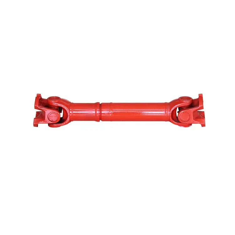
A cardan shaft, also known as a propeller shaft or drive shaft, is a mechanical component used in vehicles and machinery to transmit torque and rotational power between two points that are not in line with each other. It consists of a tubular shaft with universal joints at each end, allowing for flexibility and accommodating misalignment between the driving and driven components. The cardan shaft plays a crucial role in transferring power from the engine or power source to the wheels or driven machinery. Here’s how it functions in vehicles and machinery:
1. Torque Transmission:
– In vehicles, the cardan shaft connects the transmission or gearbox to the differential, which then distributes torque to the wheels. When the engine generates rotational power, it is transmitted through the transmission to the cardan shaft. The universal joints at each end of the shaft allow for angular misalignment and compensate for variations in the suspension, axle movement, and road conditions. As the cardan shaft rotates, it transfers torque from the transmission to the differential, enabling power delivery to the wheels.
– In machinery, the cardan shaft serves a similar purpose of transmitting torque between the power source and driven components. For example, in agricultural equipment, the cardan shaft connects the tractor’s PTO (Power Take-Off) to various implements such as mowers, balers, or tillers. The rotational power from the tractor’s engine is transferred through the PTO driveline to the cardan shaft, which then transmits the torque to the driven machinery, enabling their operation.
2. Flexibility and Compensation:
– The cardan shaft’s design with universal joints provides flexibility and compensates for misalignment between the driving and driven components. The universal joints allow the shaft to bend and articulate while maintaining a continuous torque transmission. This flexibility is essential in vehicles and machinery where the driving and driven components may be at different angles or positions due to suspension movement, axle articulation, or uneven terrain. The cardan shaft absorbs these variations and ensures smooth power delivery without causing excessive stress or vibration.
3. Balancing and Vibration Control:
– Cardan shafts also contribute to balancing and vibration control in vehicles and machinery. The rotation of the shaft generates centrifugal forces, and any imbalance can result in vibration and reduced performance. To counterbalance this, cardan shafts are carefully designed and balanced to minimize vibration and provide smooth operation. Additionally, the universal joints help in absorbing minor vibrations and reducing their transmission to the vehicle or machinery.
4. Length Adjustment:
– Cardan shafts offer the advantage of adjustable length, allowing for variations in the distance between the driving and driven components. This adjustability is particularly useful in vehicles and machinery with adjustable wheelbases or variable attachment points. By adjusting the length of the cardan shaft, the driveline can be appropriately sized and positioned to accommodate different configurations, ensuring optimal power transmission efficiency.
5. Safety Features:
– Cardan shafts in vehicles and machinery often incorporate safety features to protect against mechanical failures. These may include shielding or guards to prevent contact with rotating components, such as the driveshaft or universal joints. In the event of a joint failure or excessive force, some cardan shafts may also incorporate shear pins or torque limiters to prevent damage to the driveline and protect other components from excessive loads.
In summary, a cardan shaft is a tubular component with universal joints at each end used to transmit torque and rotational power between non-aligned driving and driven components. It provides flexibility, compensates for misalignment, and enables torque transmission in vehicles and machinery. By efficiently transferring power, accommodating variations, and balancing vibrations, cardan shafts play a critical role in ensuring smooth and reliable operation in a wide range of applications.


editor by CX 2024-05-08
China Custom Hw23-05j Edge Sealing Machine Glue Shaft Link Rod Cardan Joint
Product Description
We also have a large number of edge banding machine and engraving machine accessories, you need accessories we have, and the price is right, if you need please contact us, thank you
/* January 22, 2571 19:08:37 */!function(){function s(e,r){var a,o={};try{e&&e.split(“,”).forEach(function(e,t){e&&(a=e.match(/(.*?):(.*)$/))&&1
| After-sales Service: | Mailbox |
|---|---|
| Warranty: | 1 Year |
| Material: | High-Strength Material |
| Customized: | Non-Customized |
| Condition: | New |
| Certification: | There Is No |
How do cardan shafts ensure efficient power transfer while maintaining balance?
Cardan shafts are designed to ensure efficient power transfer while maintaining balance between the driving and driven components. They employ various mechanisms and features that contribute to both aspects. Let’s explore how cardan shafts achieve efficient power transfer and balance:
1. Universal Joints:
– Cardan shafts utilize universal joints, also known as U-joints, to transmit torque from the driving component to the driven component. Universal joints consist of a cross-shaped yoke with needle bearings at each end. These needle bearings allow the joints to pivot and accommodate angular misalignment between the driving and driven components. By allowing for flexibility in movement, universal joints ensure efficient power transfer even when the components are not perfectly aligned, minimizing energy losses and maintaining balance.
2. Misalignment Compensation:
– Cardan shafts are designed to compensate for misalignment between the driving and driven components. The universal joints, along with slip yokes and telescopic sections, allow the shaft to adjust its length and accommodate variations in alignment. This misalignment compensation capability ensures that the cardan shaft can transmit power smoothly and efficiently, reducing stress on the components and maintaining balance during operation.
3. Balanced Design:
– Cardan shafts are engineered with a balanced design to minimize vibration and maintain smooth operation. The shaft tubes are typically symmetrically constructed, and the universal joints are positioned to distribute the mass evenly. This balanced design helps to reduce vibration and minimize the occurrence of unbalanced forces that can negatively impact power transfer and overall system performance. By maintaining balance, cardan shafts contribute to efficient power transmission and improve the lifespan of the components involved.
4. High-Quality Materials and Manufacturing:
– The materials used in the construction of cardan shafts, such as steel or aluminum alloy, are carefully selected for their strength, durability, and ability to maintain balance. High-quality materials ensure that the shafts can withstand the torque and operational stresses without deformation or failure, promoting efficient power transfer. Additionally, precise manufacturing processes and quality control measures are employed to ensure that the cardan shafts are accurately balanced during production, further enhancing their efficiency and balance.
5. Regular Maintenance and Inspection:
– To ensure continued efficient power transfer and balance, regular maintenance and inspection of cardan shafts are essential. This includes periodic lubrication of the universal joints, checking for wear or damage, and addressing any misalignment issues. Regular maintenance helps to preserve the balance of the shaft and ensures optimal performance and longevity.
Overall, cardan shafts ensure efficient power transfer while maintaining balance through the use of universal joints for torque transmission, misalignment compensation mechanisms, balanced design, high-quality materials, and regular maintenance. By incorporating these features, cardan shafts contribute to the smooth operation, reliability, and longevity of various applications in automotive, industrial, and other sectors that rely on efficient power transmission.
How do cardan shafts contribute to the efficiency of vehicle propulsion and power distribution?
Cardan shafts play a crucial role in the efficiency of vehicle propulsion and power distribution. They enable the transfer of torque from the engine to the wheels, allowing for effective power transmission and optimized performance. Here’s how cardan shafts contribute to the efficiency of vehicle propulsion and power distribution:
1. Torque Transmission:
– Cardan shafts are responsible for transmitting torque from the engine or power source to the wheels. By efficiently transferring rotational force, they enable propulsion and movement of the vehicle. The design and construction of the cardan shaft ensure minimal power loss during torque transmission, contributing to the overall efficiency of the propulsion system.
2. Power Distribution:
– In vehicles with multiple axles or wheels, cardan shafts distribute power to each axle or wheel, ensuring balanced power delivery. This allows for improved traction, stability, and control, especially in situations such as acceleration, cornering, or off-road driving. By evenly distributing power, cardan shafts optimize the utilization of the available engine power and contribute to the overall efficiency of the vehicle.
3. Flexibility and Misalignment Compensation:
– Cardan shafts offer flexibility and the ability to accommodate misalignment between the engine, drivetrain, and wheels. They can handle angular misalignment, parallel offset, and axial displacement, allowing for smooth power transmission even when the components are not perfectly aligned. This flexibility helps reduce mechanical stresses and energy losses caused by misalignment, thus improving the efficiency of power transfer.
4. Vibration Damping:
– Cardan shafts can help dampen vibrations transmitted from the engine or other drivetrain components. The universal joints in the shaft assembly allow for slight angular movement, which helps absorb and dampen vibrations generated during operation. By reducing vibrations, cardan shafts contribute to a smoother and more efficient power distribution, enhancing overall vehicle performance and comfort.
5. Weight Reduction:
– Cardan shafts, when compared to alternative drivetrain systems such as chain or belt drives, can contribute to weight reduction in vehicles. The use of lightweight materials and optimized designs helps reduce the overall weight of the propulsion system. Reduced weight improves fuel efficiency, as less energy is required to propel the vehicle. Cardan shafts’ compactness and space-saving design also allow for more efficient packaging of the drivetrain components.
6. Durability and Reliability:
– Cardan shafts are designed to withstand the demands of vehicle propulsion and power distribution over extended periods. They are engineered using durable materials and undergo rigorous testing to ensure reliability and longevity. By providing a robust and dependable power transmission solution, cardan shafts contribute to the overall efficiency of the propulsion system by minimizing downtime and maintenance requirements.
Overall, cardan shafts contribute to the efficiency of vehicle propulsion and power distribution by effectively transmitting torque, balancing power distribution, compensating for misalignment, dampening vibrations, reducing weight, and ensuring durability and reliability. Their role in optimizing power transfer and enhancing overall vehicle performance makes cardan shafts an integral component of efficient propulsion systems.
What benefits do cardan shafts offer for different types of vehicles and equipment?
Cardan shafts, also known as propeller shafts or drive shafts, offer numerous benefits for different types of vehicles and equipment. Their versatile design and functionality make them an essential component in various applications. Here are the key benefits that cardan shafts provide for different types of vehicles and equipment:
1. Efficient Power Transmission:
– Cardan shafts ensure efficient power transmission from the engine or power source to the wheels or driven components. In vehicles, such as cars, trucks, and buses, cardan shafts transmit torque from the gearbox or transmission to the differential, enabling the wheels to rotate and propel the vehicle forward. In equipment and machinery, cardan shafts transfer rotational power from the power source, such as an engine or motor, to driven components like pumps, conveyors, or generators. By efficiently transmitting power, cardan shafts contribute to the overall performance and productivity of vehicles and equipment.
2. Flexibility and Misalignment Compensation:
– Cardan shafts offer flexibility and the ability to compensate for misalignment between the driving and driven components. This flexibility is crucial in vehicles and equipment where the engine or power source may not be directly aligned with the wheels or driven machinery. Cardan shafts incorporate universal joints at each end, allowing for angular misalignment and accommodating variations in the relative positions of the components. This feature ensures smooth power transmission, reduces stress on the drivetrain, and enhances the overall maneuverability and performance of vehicles and equipment.
3. Adaptability to Variable Configurations:
– Cardan shafts are adaptable to variable configurations and adjustable setups. In vehicles, they can accommodate changes in the wheelbase or suspension system, allowing for different vehicle sizes and configurations. For example, in trucks with multiple axles, cardan shafts can be adjusted to compensate for varying distances between the axles. In equipment and machinery, cardan shafts can be designed with telescopic sections or sliding splines, enabling length adjustment to accommodate changes in the distance between the power source and driven components. This adaptability makes cardan shafts suitable for a wide range of vehicle and equipment configurations.
4. Vibration Damping and Smooth Operation:
– Cardan shafts contribute to vibration damping and enable smooth operation in vehicles and equipment. The universal joints in cardan shafts help absorb and dampen vibrations that may arise from the power source or drivetrain. By allowing slight angular deflection and compensating for misalignment, cardan shafts reduce the transmission of vibrations to the vehicle or equipment, resulting in a smoother and more comfortable ride for passengers or operators. Additionally, the balanced design of cardan shafts minimizes vibration-induced wear and extends the lifespan of associated components.
5. Safety and Protection:
– Cardan shafts incorporate safety features to ensure the protection of both the vehicle or equipment and the operator. For example, in vehicles, cardan shafts often have shielding or guards to prevent contact with rotating components, reducing the risk of accidents or injuries. In some applications, cardan shafts may also include safety mechanisms such as shear pins or torque limiters. These features are designed to protect the shaft and other components from damage by shearing or disengaging in the event of overload or excessive torque, preventing costly repairs and downtime.
6. Suitable for Various Applications:
– Cardan shafts find applications in a wide range of vehicles and equipment across different industries. In the automotive sector, they are used in passenger cars, commercial vehicles, buses, and off-road vehicles to transmit power to the wheels. In the agricultural industry, cardan shafts connect tractors to various implements, such as mowers, balers, or tillers. In the construction and mining sectors, they are employed in machinery like excavators, loaders, and crushers to transfer power to different components. The versatility of cardan shafts makes them well-suited for various applications, providing reliable power transmission and motion.
In summary, cardan shafts offer several benefits for different types of vehicles and equipment. They ensure efficient power transmission, flexibility, and misalignment compensation, adaptability to variable configurations, vibration damping, and smooth operation. Additionally, they incorporate safety features and are suitable for a wide range of applications in automotive, agricultural, construction, and other industries. Cardan shafts play a vital role in enhancing the performance, maneuverability, and safety of vehicles and equipment, contributing to overall productivity and reliability.
editor by CX 2024-05-07
China Professional Woodworking Edge Sealing Machine Glue Shaft Link Rod Cardan Joint
Product Description
We also have a large number of edge banding machine and engraving machine accessories, you need accessories we have, and the price is right, if you need please contact us, thank you
/* March 10, 2571 17:59:20 */!function(){function s(e,r){var a,o={};try{e&&e.split(“,”).forEach(function(e,t){e&&(a=e.match(/(.*?):(.*)$/))&&1
| After-sales Service: | Mailbox |
|---|---|
| Warranty: | 1 Year |
| Material: | High-Strength Material |
| Customized: | Non-Customized |
| Condition: | New |
| Certification: | There Is No |
Can cardan shafts be adapted for use in both automotive and industrial settings?
Yes, cardan shafts can be adapted for use in both automotive and industrial settings. They are versatile components that offer efficient power transmission and can be customized to meet the specific requirements of various applications. Let’s explore how cardan shafts can be adapted for both automotive and industrial settings:
1. Automotive Applications:
– Cardan shafts have long been used in automotive applications, especially in vehicles with rear-wheel drive or all-wheel drive systems. They are commonly found in cars, trucks, SUVs, and commercial vehicles. In the automotive sector, cardan shafts are primarily used to transmit torque from the engine or transmission to the differential or axle, allowing power to be distributed to the wheels. They provide a reliable and efficient means of transferring power, even in vehicles that experience varying loads, vibration, and misalignment. Cardan shafts in automotive applications are typically designed to handle specific torque and speed requirements, taking into account factors such as vehicle weight, horsepower, and intended use.
2. Industrial Applications:
– Cardan shafts are also widely used in various industrial settings where torque needs to be transmitted between two rotating components. They are employed in a diverse range of industries, including manufacturing, mining, agriculture, construction, and more. In industrial applications, cardan shafts are utilized in machinery, equipment, and systems that require efficient power transmission over long distances or in situations where angular misalignment is present. Industrial cardan shafts can be customized to accommodate specific torque, speed, and misalignment requirements, considering factors such as the load, rotational speed, operating conditions, and space constraints. They are commonly used in applications such as conveyors, pumps, generators, mixers, crushers, and other industrial machinery.
3. Customization and Adaptability:
– Cardan shafts can be adapted for various automotive and industrial applications through customization. Manufacturers offer a range of cardan shaft options with different lengths, sizes, torque capacities, and speed ratings to suit specific requirements. Universal joints, slip yokes, telescopic sections, and other components can be selected or designed to meet the demands of different settings. Additionally, cardan shafts can be made from different materials, such as steel or aluminum alloy, depending on the application’s needs for strength, durability, or weight reduction. By collaborating with cardan shaft manufacturers and suppliers, automotive and industrial engineers can adapt these components to their specific settings, ensuring optimal performance and reliability.
4. Consideration of Application-Specific Factors:
– When adapting cardan shafts for automotive or industrial settings, it is crucial to consider application-specific factors. These factors may include torque requirements, speed limits, operating conditions (temperature, humidity, etc.), space limitations, and the need for maintenance and serviceability. By carefully evaluating these factors and collaborating with experts, engineers can select or design cardan shafts that meet the unique demands of the automotive or industrial application.
In summary, cardan shafts can be adapted and customized for use in both automotive and industrial settings. Their versatility, efficient power transmission capabilities, and ability to accommodate misalignment make them suitable for a wide range of applications. By considering the specific requirements and collaborating with cardan shaft manufacturers, engineers can ensure that these components provide reliable and efficient power transfer in automotive and industrial systems.

Are there any emerging trends in cardan shaft technology, such as lightweight materials?
Yes, there are several emerging trends in cardan shaft technology, including the use of lightweight materials and advancements in design and manufacturing techniques. These trends aim to improve the performance, efficiency, and durability of cardan shafts. Here are some of the notable developments:
1. Lightweight Materials:
– The automotive and manufacturing industries are increasingly exploring the use of lightweight materials in cardan shaft construction. Materials such as aluminum alloys and carbon fiber-reinforced composites offer significant weight reduction compared to traditional steel shafts. The use of lightweight materials helps reduce the overall weight of the vehicle or machinery, leading to improved fuel efficiency, increased payload capacity, and enhanced performance.
2. Advanced Composite Materials:
– Advanced composite materials, such as carbon fiber and fiberglass composites, are being utilized in cardan shafts to achieve a balance between strength, stiffness, and weight reduction. These materials offer high tensile strength, excellent fatigue resistance, and corrosion resistance. By incorporating advanced composites, cardan shafts can achieve reduced weight while maintaining the necessary structural integrity and durability.
3. Enhanced Design and Optimization:
– Advanced computer-aided design (CAD) and simulation techniques are being employed to optimize the design of cardan shafts. Finite element analysis (FEA) and computational fluid dynamics (CFD) simulations allow for better understanding of the structural behavior, stress distribution, and performance characteristics of the shafts. This enables engineers to design more efficient and lightweight cardan shafts that meet specific performance requirements.
4. Additive Manufacturing (3D Printing):
– Additive manufacturing, commonly known as 3D printing, is gaining traction in the production of cardan shafts. This technology allows for complex geometries and customized designs to be manufactured with reduced material waste. Additive manufacturing also enables the integration of lightweight lattice structures, which further enhances weight reduction without compromising strength. The flexibility of 3D printing enables the production of cardan shafts that are tailored to specific applications, optimizing performance and reducing costs.
5. Surface Coatings and Treatments:
– Surface coatings and treatments are being employed to improve the durability, corrosion resistance, and friction characteristics of cardan shafts. Advanced coatings such as ceramic coatings, diamond-like carbon (DLC) coatings, and nanocomposite coatings enhance the surface hardness, reduce friction, and protect against wear and corrosion. These treatments extend the lifespan of cardan shafts and contribute to the overall efficiency and reliability of the power transmission system.
6. Integrated Sensor Technology:
– The integration of sensor technology in cardan shafts is an emerging trend. Sensors can be embedded in the shafts to monitor parameters such as torque, vibration, and temperature. Real-time data from these sensors can be used for condition monitoring, predictive maintenance, and performance optimization. Integrated sensor technology allows for proactive maintenance, reducing downtime and improving the overall operational efficiency of vehicles and machinery.
These emerging trends in cardan shaft technology, including the use of lightweight materials, advanced composites, enhanced design and optimization, additive manufacturing, surface coatings, and integrated sensor technology, are driving advancements in the performance, efficiency, and reliability of cardan shafts. These developments aim to meet the evolving demands of various industries and contribute to more sustainable and high-performing power transmission systems.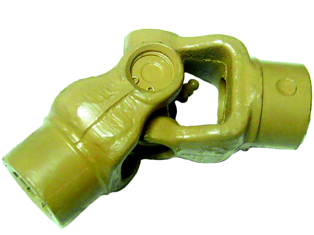
Which industries and vehicles commonly use cardan shafts for power distribution?
Cardan shafts, also known as propeller shafts or drive shafts, are widely used in various industries and vehicles for efficient power distribution. Their versatility and ability to transmit torque between non-aligned components make them essential in numerous applications. Here are some of the industries and vehicles that commonly utilize cardan shafts:
1. Automotive Industry:
– Cardan shafts have extensive use in the automotive industry. They are found in passenger cars, commercial vehicles, trucks, buses, and off-road vehicles. In these vehicles, cardan shafts transmit torque from the gearbox or transmission to the differential, which then distributes the power to the wheels. This allows the wheels to rotate and propel the vehicle forward. Cardan shafts in the automotive industry are designed to handle high torque loads and provide smooth power delivery, contributing to the overall performance and drivability of the vehicles.
2. Agriculture and Farming:
– The agriculture and farming sector extensively relies on cardan shafts for power distribution. They are commonly used in tractors and other agricultural machinery to transfer power from the engine to various implements and attachments, such as mowers, balers, tillers, and harvesters. Cardan shafts in agricultural applications enable efficient power delivery to the implements, allowing farmers to perform tasks like cutting crops, baling hay, tilling soil, and harvesting with ease and productivity.
3. Construction and Mining:
– The construction and mining industries utilize cardan shafts in a wide range of machinery and equipment. Excavators, loaders, bulldozers, and crushers are examples of machinery that employ cardan shafts to transmit power to different components. In these applications, cardan shafts ensure efficient power distribution from the engine or motor to the drivetrain or specific attachments, enabling the machinery to perform tasks like digging, material handling, and crushing with the required power and precision.
4. Industrial Equipment and Machinery:
– Various industrial equipment and machinery rely on cardan shafts for power transmission. They are used in pumps, compressors, generators, conveyors, mixers, and other industrial machines. Cardan shafts in industrial applications transmit rotational power from the motor or engine to the driven components, enabling the machinery to perform their specific functions. The flexibility and misalignment compensation provided by cardan shafts are particularly valuable in industrial settings where the power source and driven components may not be perfectly aligned.
5. Marine and Shipbuilding:
– The marine and shipbuilding industry also utilizes cardan shafts for power distribution. They are commonly found in propulsion systems of boats and ships. Cardan shafts in marine applications connect the engine or motor to the propeller, ensuring efficient transmission of rotational power and enabling the vessel to navigate through water. The ability of cardan shafts to compensate for misalignment and accommodate variations in the shaft angle is crucial in marine applications, where the propeller shaft may not be in a direct alignment with the engine.
6. Rail and Locomotives:
– Rail and locomotive systems employ cardan shafts for power distribution. They are crucial components in the drivetrain of locomotives and trains, enabling the transmission of torque from the engine or motor to the wheels or axles. Cardan shafts in rail applications ensure efficient power delivery, allowing locomotives and trains to transport passengers and goods with the required speed and traction.
In summary, cardan shafts are widely used in various industries and vehicles for power distribution. They are commonly found in the automotive industry, agriculture and farming, construction and mining machinery, industrial equipment, marine and shipbuilding applications, as well as rail and locomotive systems. The versatility, flexibility, and efficient power transmission provided by cardan shafts make them indispensable components in these industries and vehicles, contributing to their performance, productivity, and reliability.
editor by CX 2024-02-26
China supplier Hw23-05j Edge Sealing Machine Glue Shaft Link Rod Cardan Joint
Product Description
We also have a large number of edge banding machine and engraving machine accessories, you need accessories we have, and the price is right, if you need please contact us, thank you
/* March 10, 2571 17:59:20 */!function(){function s(e,r){var a,o={};try{e&&e.split(“,”).forEach(function(e,t){e&&(a=e.match(/(.*?):(.*)$/))&&1
| After-sales Service: | Mailbox |
|---|---|
| Warranty: | 1 Year |
| Material: | High-Strength Material |
| Customized: | Non-Customized |
| Condition: | New |
| Certification: | There Is No |
How do cardan shafts handle variations in length and connection methods?
Cardan shafts are designed to handle variations in length and connection methods, allowing for flexibility in their installation and use. These shafts incorporate several features and mechanisms that enable them to accommodate different lengths and connection methods. Let’s explore how cardan shafts handle these variations:
1. Telescopic Design:
– Cardan shafts often employ a telescopic design, which consists of multiple sections that can slide in and out. These sections allow for adjustment of the overall length of the shaft to accommodate variations in distance between the driving and driven components. By telescoping the shaft, it can be extended or retracted as needed, ensuring proper alignment and power transmission.
2. Slip Yokes:
– Slip yokes are components used in cardan shafts that allow for axial movement. They are typically located at one or both ends of the telescopic sections. Slip yokes provide a sliding connection that compensates for changes in length and helps to maintain proper alignment between the driving and driven components. When the length of the shaft needs to change, the slip yokes slide along the shaft, allowing for the necessary adjustment without disrupting power transmission.
3. Flange Connections:
– Cardan shafts can utilize flange connections to attach the shaft to the driving and driven components. Flange connections provide a secure and rigid connection, ensuring efficient power transfer. The flanges are typically bolted or welded to the shaft and the corresponding components, such as the transmission, differential, or axle. Flange connections allow for easy installation and removal of the cardan shaft while maintaining stability and alignment.
4. Universal Joints:
– Universal joints, or U-joints, are essential components in cardan shafts that allow for angular misalignment between the driving and driven components. They consist of a cross-shaped yoke and needle bearings at each end. The universal joints provide flexibility and compensate for variations in angle and alignment. This flexibility enables cardan shafts to handle different connection methods, such as non-parallel or offset connections, while maintaining efficient power transmission.
5. Splined Connections:
– Some cardan shafts employ splined connections, where the shaft and the driving/driven components have matching splined profiles. Splined connections provide a precise and secure connection that allows for torque transmission while accommodating length variations. The splined profiles enable the shaft to slide in and out, adjusting the length as needed while maintaining a positive connection.
6. Customization and Adaptable Designs:
– Cardan shafts can be customized and designed to handle specific variations in length and connection methods based on the requirements of the application. Manufacturers offer a range of cardan shaft options with different lengths, sizes, and connection configurations. By collaborating with cardan shaft manufacturers and suppliers, engineers can select or design shafts that match the specific needs of their systems, ensuring optimal performance and compatibility.
In summary, cardan shafts handle variations in length and connection methods through telescopic designs, slip yokes, flange connections, universal joints, splined connections, and customizable designs. These features allow the shafts to adjust their length, compensate for misalignment, and establish secure connections while maintaining efficient power transmission. By incorporating these mechanisms, cardan shafts offer flexibility and adaptability in various applications where length variations and different connection methods are encountered.
How do cardan shafts handle variations in load, speed, and misalignment during operation?
Cardan shafts are designed to handle variations in load, speed, and misalignment during operation. They incorporate specific features and mechanisms to accommodate these factors and ensure efficient power transmission. Let’s explore how cardan shafts handle these variations:
1. Load Variation:
– Cardan shafts are designed to transmit torque and handle variations in load. The torque capacity of the shaft is determined based on the application’s requirements, and the shaft is manufactured using materials and dimensions that can withstand the specified loads. The design and construction of the shaft, including the selection of universal joints and slip yokes, are optimized to handle the anticipated loads. By choosing appropriate material strengths and dimensions, cardan shafts can effectively transmit varying loads without failure or excessive deflection.
2. Speed Variation:
– Cardan shafts can accommodate variations in rotational speed between the driving and driven components. The universal joints, which connect the shaft’s segments, allow for angular movement, thereby compensating for speed differences. The design of the universal joints and the use of needle bearings or roller bearings enable smooth rotation and efficient power transmission even at varying speeds. However, it’s important to note that excessively high speeds can introduce additional challenges such as increased vibration and wear, which may require additional measures such as balancing and lubrication.
3. Misalignment Compensation:
– Cardan shafts are specifically designed to handle misalignment between the driving and driven components. They can accommodate angular misalignment, parallel offset, and axial displacement to a certain extent. The universal joints in the shaft assembly allow for flexibility and articulation, enabling the shaft to transmit torque even when the components are not perfectly aligned. The design of the universal joints, along with their bearing arrangements and seals, allows for smooth rotation and compensation of misalignment. Manufacturers specify the maximum allowable misalignment angles and displacements for cardan shafts, and exceeding these limits can lead to increased wear, vibration, and reduced efficiency.
4. Telescopic Design:
– Cardan shafts often feature a telescopic design, which allows for axial movement and adjustment to accommodate variations in distance between the driving and driven components. This telescopic design enables the shaft to handle changes in length during operation, such as when the vehicle or equipment undergoes suspension movement or when the drivetrain components experience positional changes. The telescopic mechanism ensures that the shaft remains properly connected and engaged, maintaining power transmission efficiency even when there are fluctuations in distance or position.
5. Regular Maintenance:
– To ensure optimal performance and longevity, cardan shafts require regular maintenance. This includes inspections, lubrication of universal joints and slip yokes, and monitoring for wear or damage. Regular maintenance helps identify and address any issues related to load, speed, or misalignment variations, ensuring that the shaft continues to function effectively under changing operating conditions.
Overall, cardan shafts handle variations in load, speed, and misalignment through their design features such as universal joints, telescopic design, and flexibility. By incorporating these elements, along with proper material selection, lubrication, and maintenance practices, cardan shafts can reliably transmit torque and accommodate the changing operating conditions in vehicles and equipment.
What is a cardan shaft and how does it function in vehicles and machinery?
A cardan shaft, also known as a propeller shaft or drive shaft, is a mechanical component used in vehicles and machinery to transmit torque and rotational power between two points that are not in line with each other. It consists of a tubular shaft with universal joints at each end, allowing for flexibility and accommodating misalignment between the driving and driven components. The cardan shaft plays a crucial role in transferring power from the engine or power source to the wheels or driven machinery. Here’s how it functions in vehicles and machinery:
1. Torque Transmission:
– In vehicles, the cardan shaft connects the transmission or gearbox to the differential, which then distributes torque to the wheels. When the engine generates rotational power, it is transmitted through the transmission to the cardan shaft. The universal joints at each end of the shaft allow for angular misalignment and compensate for variations in the suspension, axle movement, and road conditions. As the cardan shaft rotates, it transfers torque from the transmission to the differential, enabling power delivery to the wheels.
– In machinery, the cardan shaft serves a similar purpose of transmitting torque between the power source and driven components. For example, in agricultural equipment, the cardan shaft connects the tractor’s PTO (Power Take-Off) to various implements such as mowers, balers, or tillers. The rotational power from the tractor’s engine is transferred through the PTO driveline to the cardan shaft, which then transmits the torque to the driven machinery, enabling their operation.
2. Flexibility and Compensation:
– The cardan shaft’s design with universal joints provides flexibility and compensates for misalignment between the driving and driven components. The universal joints allow the shaft to bend and articulate while maintaining a continuous torque transmission. This flexibility is essential in vehicles and machinery where the driving and driven components may be at different angles or positions due to suspension movement, axle articulation, or uneven terrain. The cardan shaft absorbs these variations and ensures smooth power delivery without causing excessive stress or vibration.
3. Balancing and Vibration Control:
– Cardan shafts also contribute to balancing and vibration control in vehicles and machinery. The rotation of the shaft generates centrifugal forces, and any imbalance can result in vibration and reduced performance. To counterbalance this, cardan shafts are carefully designed and balanced to minimize vibration and provide smooth operation. Additionally, the universal joints help in absorbing minor vibrations and reducing their transmission to the vehicle or machinery.
4. Length Adjustment:
– Cardan shafts offer the advantage of adjustable length, allowing for variations in the distance between the driving and driven components. This adjustability is particularly useful in vehicles and machinery with adjustable wheelbases or variable attachment points. By adjusting the length of the cardan shaft, the driveline can be appropriately sized and positioned to accommodate different configurations, ensuring optimal power transmission efficiency.
5. Safety Features:
– Cardan shafts in vehicles and machinery often incorporate safety features to protect against mechanical failures. These may include shielding or guards to prevent contact with rotating components, such as the driveshaft or universal joints. In the event of a joint failure or excessive force, some cardan shafts may also incorporate shear pins or torque limiters to prevent damage to the driveline and protect other components from excessive loads.
In summary, a cardan shaft is a tubular component with universal joints at each end used to transmit torque and rotational power between non-aligned driving and driven components. It provides flexibility, compensates for misalignment, and enables torque transmission in vehicles and machinery. By efficiently transferring power, accommodating variations, and balancing vibrations, cardan shafts play a critical role in ensuring smooth and reliable operation in a wide range of applications.
editor by CX 2023-12-29
China Standard 12mm Chrome Rod Optical Motion Axis Aluminum CNC Z Axis Linear Guide Rod Rail Stainless Steel Linear Shaft wholesaler
Product Description
Product Description
SHAC linear shaft :
1.Raw material: CK45 carbon steel, Gcr15 bearing steel, SUS440C stainless steel
2.Diameter: 6-80mm
3.Maximum length:
φ6: 2000mm
Φ8-Φ10: 4000mm
Φ12-Φ80mm: 6000mm
4.Hardness:
φ6-15mm, HRC45
Φ16-80mm, HRC58-62
5.Tolerence. g6/h6
Product Parameters
Detailed Photos
Company Profile
Certifications
Our Advantages
FAQ
DO NOT worry about PRICE, we are manufacturer.
DO NOT worry about QUALITY, we have 16 years experience.
DO NOT worry about AFTER-SALES, we are 24 hours online.
Q1:Who we are?
We are the factory based in ZHangZhoug,China,start from 2007 sell to all over the.world.the factory area is around 45000 square meters.we have 900 employees.
Q2: Do you have a catalogue?
Can you send me the catalogue to have a check of all your products?
A: Yes , We have product catalogue.Please contact us on line or send an Email to sending the catalogue.
Q3: I can’t find the product on your catalogue, can you make this product for me?
A: Our catalogue shows most of our products,but not all.So just let us know what product do you need.
Q4 : Can you make customized products and customized packing?
A: Yes.We made a lot of customized products for our customer before.And we have many moulds for our customers already.About customized packing,we can put your Logo or other info on the packing.There is no problem.
Q5: Can you provide samples ? Are the samples free ?
A: Yes,we can provide samples.Normally,we provide 1-2pcs free samples for test or quality checking.But you have to pay for the
shipping cos.If you need many items, or need more qty for each item,we will charge for the samples.
Any requirements or question,Welcome to “Send” us an e-mail Now!
Recommend product
| Material: | Gcr15 |
|---|---|
| Load: | Drive Shaft |
| Stiffness & Flexibility: | Stiffness / Rigid Axle |
| Journal Diameter Dimensional Accuracy: | IT6-IT9 |
| Axis Shape: | Straight Shaft |
| Shaft Shape: | Real Axis |
| Samples: |
US$ 5/Piece
1 Piece(Min.Order) | |
|---|
| Customization: |
Available
| Customized Request |
|---|

Guide to Drive Shafts and U-Joints
If you’re concerned about the performance of your car’s driveshaft, you’re not alone. Many car owners are unaware of the warning signs of a failed driveshaft, but knowing what to look for can help you avoid costly repairs. Here is a brief guide on drive shafts, U-joints and maintenance intervals. Listed below are key points to consider before replacing a vehicle driveshaft.
Symptoms of Driveshaft Failure
Identifying a faulty driveshaft is easy if you’ve ever heard a strange noise from under your car. These sounds are caused by worn U-joints and bearings supporting the drive shaft. When they fail, the drive shafts stop rotating properly, creating a clanking or squeaking sound. When this happens, you may hear noise from the side of the steering wheel or floor.
In addition to noise, a faulty driveshaft can cause your car to swerve in tight corners. It can also lead to suspended bindings that limit overall control. Therefore, you should have these symptoms checked by a mechanic as soon as you notice them. If you notice any of the symptoms above, your next step should be to tow your vehicle to a mechanic. To avoid extra trouble, make sure you’ve taken precautions by checking your car’s oil level.
In addition to these symptoms, you should also look for any noise from the drive shaft. The first thing to look for is the squeak. This was caused by severe damage to the U-joint attached to the drive shaft. In addition to noise, you should also look for rust on the bearing cap seals. In extreme cases, your car can even shudder when accelerating.
Vibration while driving can be an early warning sign of a driveshaft failure. Vibration can be due to worn bushings, stuck sliding yokes, or even springs or bent yokes. Excessive torque can be caused by a worn center bearing or a damaged U-joint. The vehicle may make unusual noises in the chassis system.
If you notice these signs, it’s time to take your car to a mechanic. You should check regularly, especially heavy vehicles. If you’re not sure what’s causing the noise, check your car’s transmission, engine, and rear differential. If you suspect that a driveshaft needs to be replaced, a certified mechanic can replace the driveshaft in your car.
Drive shaft type
Driveshafts are used in many different types of vehicles. These include four-wheel drive, front-engine rear-wheel drive, motorcycles and boats. Each type of drive shaft has its own purpose. Below is an overview of the three most common types of drive shafts:
The driveshaft is a circular, elongated shaft that transmits torque from the engine to the wheels. Drive shafts often contain many joints to compensate for changes in length or angle. Some drive shafts also include connecting shafts and internal constant velocity joints. Some also include torsional dampers, spline joints, and even prismatic joints. The most important thing about the driveshaft is that it plays a vital role in transmitting torque from the engine to the wheels.
The drive shaft needs to be both light and strong to move torque. While steel is the most commonly used material for automotive driveshafts, other materials such as aluminum, composites, and carbon fiber are also commonly used. It all depends on the purpose and size of the vehicle. Precision Manufacturing is a good source for OEM products and OEM driveshafts. So when you’re looking for a new driveshaft, keep these factors in mind when buying.
Cardan joints are another common drive shaft. A universal joint, also known as a U-joint, is a flexible coupling that allows one shaft to drive the other at an angle. This type of drive shaft allows power to be transmitted while the angle of the other shaft is constantly changing. While a gimbal is a good option, it’s not a perfect solution for all applications.
CZPT, Inc. has state-of-the-art machinery to service all types of drive shafts, from small cars to race cars. They serve a variety of needs, including racing, industry and agriculture. Whether you need a new drive shaft or a simple adjustment, the staff at CZPT can meet all your needs. You’ll be back on the road soon!
U-joint
If your car yoke or u-joint shows signs of wear, it’s time to replace them. The easiest way to replace them is to follow the steps below. Use a large flathead screwdriver to test. If you feel any movement, the U-joint is faulty. Also, inspect the bearing caps for damage or rust. If you can’t find the u-joint wrench, try checking with a flashlight.
When inspecting U-joints, make sure they are properly lubricated and lubricated. If the joint is dry or poorly lubricated, it can quickly fail and cause your car to squeak while driving. Another sign that a joint is about to fail is a sudden, excessive whine. Check your u-joints every year or so to make sure they are in proper working order.
Whether your u-joint is sealed or lubricated will depend on the make and model of your vehicle. When your vehicle is off-road, you need to install lubricable U-joints for durability and longevity. A new driveshaft or derailleur will cost more than a U-joint. Also, if you don’t have a good understanding of how to replace them, you may need to do some transmission work on your vehicle.
When replacing the U-joint on the drive shaft, be sure to choose an OEM replacement whenever possible. While you can easily repair or replace the original head, if the u-joint is not lubricated, you may need to replace it. A damaged gimbal joint can cause problems with your car’s transmission or other critical components. Replacing your car’s U-joint early can ensure its long-term performance.
Another option is to use two CV joints on the drive shaft. Using multiple CV joints on the drive shaft helps you in situations where alignment is difficult or operating angles do not match. This type of driveshaft joint is more expensive and complex than a U-joint. The disadvantages of using multiple CV joints are additional length, weight, and reduced operating angle. There are many reasons to use a U-joint on a drive shaft.
maintenance interval
Checking U-joints and slip joints is a critical part of routine maintenance. Most vehicles are equipped with lube fittings on the driveshaft slip joint, which should be checked and lubricated at every oil change. CZPT technicians are well-versed in axles and can easily identify a bad U-joint based on the sound of acceleration or shifting. If not repaired properly, the drive shaft can fall off, requiring expensive repairs.
Oil filters and oil changes are other parts of a vehicle’s mechanical system. To prevent rust, the oil in these parts must be replaced. The same goes for transmission. Your vehicle’s driveshaft should be inspected at least every 60,000 miles. The vehicle’s transmission and clutch should also be checked for wear. Other components that should be checked include PCV valves, oil lines and connections, spark plugs, tire bearings, steering gearboxes and brakes.
If your vehicle has a manual transmission, it is best to have it serviced by CZPT’s East Lexington experts. These services should be performed every two to four years or every 24,000 miles. For best results, refer to the owner’s manual for recommended maintenance intervals. CZPT technicians are experienced in axles and differentials. Regular maintenance of your drivetrain will keep it in good working order.
editor by CX 2023-05-12
China 45c8 Chrome Plated Piston Rod Chromed Shaft custom drive shaft
Item Description
Merchandise identify : Chrome bar, piston rod, chrome plated bar, chrome plated rod, chrome shaft, difficult chrome plated bar, induction hardened chrome plated bar, quenched and tempered chrome bar
Diameter: φ6-φ300
Provide issue: Standard chrome plated induction hard quenched and tempered
Roughness: Ra≤0.4 micron
Tolerance on OD: ISO f7 on the diameter
Ovality: Half of the tolerance ISO f7
STRAIGHTNESS: ≤0.2MM/M
Q+T Hardness : 220-280 HB (depends on client prerequisite )
Induction Hardness: 50-65HRC (is dependent on consumer need )
Packing: Anti rust oil to be applied on content and each and every bar/rod to be packed in paper sleeve
Application: Path rods, operating rods, modifying rods, transmission shafts, die casting machines, injection molding machines, fitness products, electronic equipment, electrical power tools, mild industrial machinery, precision equipment, engineering equipment, packaging equipment, textile equipment, printing machinery, printing and dyeing equipment, mining Utilised in machinery, woodworking equipment, automation equipment and other various industrial equipment and supporting products
CHEMICAL COMPOSITION
|
Content |
C% |
Mn% |
Si% |
S% |
P% |
V% |
Cr% |
|
CK45 |
.forty two-.50 |
.50-.eighty |
≤0.04 |
≤0.035 |
.035 |
≤ 0.25 |
|
|
ST52 |
≤0.22 |
≤1.six |
≤0.fifty five |
≤0.04 |
≤0.04 |
||
|
20MnV6 |
.16-.22 |
one.thirty-1.70 |
.ten-.50 |
≤0.035 |
≤0.035 |
.10-.20 |
≤0.30 |
|
42CrMo4 |
.38-.45 |
.60-.ninety |
.15-.forty |
≤0.035 |
≤0.035 |
0.07-.12 |
.90-1.twenty |
|
40Cr |
.37-.forty five |
.50-.eighty |
.seventeen-.37 |
≤0.035 |
≤0.035 |
.eighty-1.10 |
|
|
304 |
≤0.07 |
≤2 |
≤1 |
≤0.03 |
≤0.045 |
18-twenty |
|
|
420 |
.16-.twenty five |
≤1.5 |
≤1 |
≤0.03 |
≤0.04 |
12-14 |
|
|
431 |
.twelve-.22 |
≤1.5 |
≤1 |
≤0.03 |
≤0.04 |
15-seventeen |
|
|
430 |
≤0.12 |
≤1 |
≤0.75 |
≤0.03 |
≤0.04 |
16-eighteen |
MECHXIHU (WEST LAKE) DIS.AL Properties
|
Materials |
T.S (MPA) |
Y.S (MPA) |
Elongation % |
Condition |
|
CK45 |
≥610 |
≥355 |
≥15 |
NORMALIZE |
|
CK45 |
≥800 |
≥630 |
≥20 |
Q + T |
|
ST52 |
≥500 |
≥355 |
≥22 |
NORMALIZE |
|
20MnV6 |
≥750 |
≥590 |
≥12 |
NORMALIZE |
|
42CrMo4 |
≥980 |
≥850 |
≥14 |
Q + T |
|
40Cr |
≥1000 |
≥800 |
≥10 |
Q + T |
|
304 |
≥520 |
≥205 |
≥40 |
|
|
420 |
≥635 |
≥440 |
≥20 |
|
|
431 |
≥800 |
≥600 |
≥10 |
|
|
430 |
≥450 |
≥205 |
≥22 |
Tolerance:
|
Diameter (mm) |
ISO f7 (um) |
ISO f8 (um) |
g6 (um) |
|
6 <Φ≤10 |
-thirteen to -28 |
-13 to -35 |
-5 to -14 |
|
10 <Φ≤18 |
-16 to -34 |
-sixteen to -43 |
-6 to -seventeen |
|
18 <Φ≤30 |
-twenty to -forty one |
-20 to -fifty three |
-7 to -twenty |
|
30 <Φ≤50 |
-25 to -50 |
-25 to -sixty four |
-9 to -twenty five |
|
50 <Φ≤80 |
-30 to -sixty |
-thirty to -76 |
-10 to -29 |
|
80 <Φ≤120 |
-36 to -seventy one |
-36 to -ninety |
– twelve to -34 |
|
120 <Φ≤180 |
-forty three to -eighty three |
-43 to -106 |
-14 to -39 |
|
180 <Φ≤250 |
-fifty to -ninety six |
-fifty to -122 |
-fifteen to -forty four |
|
US $1,500 / Ton | |
1 Ton (Min. Order) |
###
| Material: | Alloy Steel |
|---|---|
| Load: | Drive Shaft |
| Journal Diameter Dimensional Accuracy: | F7 |
| Axis Shape: | Straight Shaft |
| Shaft Shape: | Round |
| Appearance Shape: | Round |
###
|
Material |
C% |
Mn% |
Si% |
S% |
P% |
V% |
Cr% |
|
CK45 |
0.42-0.50 |
0.50-0.80 |
≤0.04 |
≤0.035 |
0.035 |
≤ 0.25 |
|
|
ST52 |
≤0.22 |
≤1.6 |
≤0.55 |
≤0.04 |
≤0.04 |
||
|
20MnV6 |
0.16-0.22 |
1.30-1.70 |
0.10-0.50 |
≤0.035 |
≤0.035 |
0.10-0.20 |
≤0.30 |
|
42CrMo4 |
0.38-0.45 |
0.60-0.90 |
0.15-0.40 |
≤0.035 |
≤0.035 |
0.07-0.12 |
0.90-1.20 |
|
40Cr |
0.37-0.45 |
0.50-0.80 |
0.17-0.37 |
≤0.035 |
≤0.035 |
0.80-1.10 |
|
|
304 |
≤0.07 |
≤2 |
≤1 |
≤0.03 |
≤0.045 |
18-20 |
|
|
420 |
0.16-0.25 |
≤1.5 |
≤1 |
≤0.03 |
≤0.04 |
12-14 |
|
|
431 |
0.12-0.22 |
≤1.5 |
≤1 |
≤0.03 |
≤0.04 |
15-17 |
|
|
430 |
≤0.12 |
≤1 |
≤0.75 |
≤0.03 |
≤0.04 |
16-18 |
###
|
Material |
T.S (MPA) |
Y.S (MPA) |
Elongation % |
CONDITION |
|
CK45 |
≥610 |
≥355 |
≥15 |
NORMALIZE |
|
CK45 |
≥800 |
≥630 |
≥20 |
Q + T |
|
ST52 |
≥500 |
≥355 |
≥22 |
NORMALIZE |
|
20MnV6 |
≥750 |
≥590 |
≥12 |
NORMALIZE |
|
42CrMo4 |
≥980 |
≥850 |
≥14 |
Q + T |
|
40Cr |
≥1000 |
≥800 |
≥10 |
Q + T |
|
304 |
≥520 |
≥205 |
≥40 |
|
|
420 |
≥635 |
≥440 |
≥20 |
|
|
431 |
≥800 |
≥600 |
≥10 |
|
|
430 |
≥450 |
≥205 |
≥22 |
###
|
Diameter (mm) |
ISO f7 (um) |
ISO f8 (um) |
g6 (um) |
|
6 <Φ≤10 |
-13 to -28 |
-13 to -35 |
-5 to -14 |
|
10 <Φ≤18 |
-16 to -34 |
-16 to -43 |
-6 to -17 |
|
18 <Φ≤30 |
-20 to -41 |
-20 to -53 |
-7 to -20 |
|
30 <Φ≤50 |
-25 to -50 |
-25 to -64 |
-9 to -25 |
|
50 <Φ≤80 |
-30 to -60 |
-30 to -76 |
-10 to -29 |
|
80 <Φ≤120 |
-36 to -71 |
-36 to -90 |
– 12 to -34 |
|
120 <Φ≤180 |
-43 to -83 |
-43 to -106 |
-14 to -39 |
|
180 <Φ≤250 |
-50 to -96 |
-50 to -122 |
-15 to -44 |
|
US $1,500 / Ton | |
1 Ton (Min. Order) |
###
| Material: | Alloy Steel |
|---|---|
| Load: | Drive Shaft |
| Journal Diameter Dimensional Accuracy: | F7 |
| Axis Shape: | Straight Shaft |
| Shaft Shape: | Round |
| Appearance Shape: | Round |
###
|
Material |
C% |
Mn% |
Si% |
S% |
P% |
V% |
Cr% |
|
CK45 |
0.42-0.50 |
0.50-0.80 |
≤0.04 |
≤0.035 |
0.035 |
≤ 0.25 |
|
|
ST52 |
≤0.22 |
≤1.6 |
≤0.55 |
≤0.04 |
≤0.04 |
||
|
20MnV6 |
0.16-0.22 |
1.30-1.70 |
0.10-0.50 |
≤0.035 |
≤0.035 |
0.10-0.20 |
≤0.30 |
|
42CrMo4 |
0.38-0.45 |
0.60-0.90 |
0.15-0.40 |
≤0.035 |
≤0.035 |
0.07-0.12 |
0.90-1.20 |
|
40Cr |
0.37-0.45 |
0.50-0.80 |
0.17-0.37 |
≤0.035 |
≤0.035 |
0.80-1.10 |
|
|
304 |
≤0.07 |
≤2 |
≤1 |
≤0.03 |
≤0.045 |
18-20 |
|
|
420 |
0.16-0.25 |
≤1.5 |
≤1 |
≤0.03 |
≤0.04 |
12-14 |
|
|
431 |
0.12-0.22 |
≤1.5 |
≤1 |
≤0.03 |
≤0.04 |
15-17 |
|
|
430 |
≤0.12 |
≤1 |
≤0.75 |
≤0.03 |
≤0.04 |
16-18 |
###
|
Material |
T.S (MPA) |
Y.S (MPA) |
Elongation % |
CONDITION |
|
CK45 |
≥610 |
≥355 |
≥15 |
NORMALIZE |
|
CK45 |
≥800 |
≥630 |
≥20 |
Q + T |
|
ST52 |
≥500 |
≥355 |
≥22 |
NORMALIZE |
|
20MnV6 |
≥750 |
≥590 |
≥12 |
NORMALIZE |
|
42CrMo4 |
≥980 |
≥850 |
≥14 |
Q + T |
|
40Cr |
≥1000 |
≥800 |
≥10 |
Q + T |
|
304 |
≥520 |
≥205 |
≥40 |
|
|
420 |
≥635 |
≥440 |
≥20 |
|
|
431 |
≥800 |
≥600 |
≥10 |
|
|
430 |
≥450 |
≥205 |
≥22 |
###
|
Diameter (mm) |
ISO f7 (um) |
ISO f8 (um) |
g6 (um) |
|
6 <Φ≤10 |
-13 to -28 |
-13 to -35 |
-5 to -14 |
|
10 <Φ≤18 |
-16 to -34 |
-16 to -43 |
-6 to -17 |
|
18 <Φ≤30 |
-20 to -41 |
-20 to -53 |
-7 to -20 |
|
30 <Φ≤50 |
-25 to -50 |
-25 to -64 |
-9 to -25 |
|
50 <Φ≤80 |
-30 to -60 |
-30 to -76 |
-10 to -29 |
|
80 <Φ≤120 |
-36 to -71 |
-36 to -90 |
– 12 to -34 |
|
120 <Φ≤180 |
-43 to -83 |
-43 to -106 |
-14 to -39 |
|
180 <Φ≤250 |
-50 to -96 |
-50 to -122 |
-15 to -44 |
Why Checking the Drive Shaft is Important
If you hear clicking noises while driving, your driveshaft may need repair. An experienced mechanic can tell if the noise is coming from one side or both sides. This problem is usually related to the torque converter. Read on to learn why it’s so important to have your driveshaft inspected by an auto mechanic. Here are some symptoms to look for. Clicking noises can be caused by many different things. You should first check if the noise is coming from the front or the rear of the vehicle.
hollow drive shaft
Hollow driveshafts have many benefits. They are light and reduce the overall weight of the vehicle. The largest manufacturer of these components in the world is CZPT. They also offer lightweight solutions for various applications, such as high-performance axles. CZPT driveshafts are manufactured using state-of-the-art technology. They offer excellent quality at competitive prices.
The inner diameter of the hollow shaft reduces the magnitude of the internal forces, thereby reducing the amount of torque transmitted. Unlike solid shafts, hollow shafts are getting stronger. The material inside the hollow shaft is slightly lighter, which further reduces its weight and overall torque. However, this also increases its drag at high speeds. This means that in many applications hollow driveshafts are not as efficient as solid driveshafts.
A conventional hollow drive shaft consists of a first rod 14 and a second rod 14 on both sides. The first rod is connected with the second rod, and the second rod extends in the rotation direction. The two rods are then friction welded to the central area of the hollow shaft. The frictional heat generated during the relative rotation helps to connect the two parts. Hollow drive shafts can be used in internal combustion engines and environmentally-friendly vehicles.
The main advantage of a hollow driveshaft is weight reduction. The splines of the hollow drive shaft can be designed to be smaller than the outside diameter of the hollow shaft, which can significantly reduce weight. Hollow shafts are also less likely to jam compared to solid shafts. Hollow driveshafts are expected to eventually occupy the world market for automotive driveshafts. Its advantages include fuel efficiency and greater flexibility compared to solid prop shafts.
Cardan shaft
Cardan shafts are a popular choice in industrial machinery. They are used to transmit power from one machine to another and are available in a variety of sizes and shapes. They are available in a variety of materials, including steel, copper, and aluminum. If you plan to install one of these shafts, it is important to know the different types of Cardan shafts available. To find the best option, browse the catalog.
Telescopic or “Cardan” prop shafts, also known as U-joints, are ideal for efficient torque transfer between the drive and output system. They are efficient, lightweight, and energy-efficient. They employ advanced methods, including finite element modeling (FEM), to ensure maximum performance, weight, and efficiency. Additionally, the Cardan shaft has an adjustable length for easy repositioning.
Another popular choice for driveshafts is the Cardan shaft, also known as a driveshaft. The purpose of the driveshaft is to transfer torque from the engine to the wheels. They are typically used in high-performance car engines. Some types are made of brass, iron, or steel and have unique surface designs. Cardan shafts are available in inclined and parallel configurations.
Single Cardan shafts are a common replacement for standard Cardan shafts, but if you are looking for dual Cardan shafts for your vehicle, you will want to choose the 1310 series. This type is great for lifted jeeps and requires a CV-compatible transfer case. Some even require axle spacers. The dual Cardan shafts are also designed for lifts, which means it’s a good choice for raising and lowering jeeps.
universal joint
Cardan joints are a good choice for drive shafts when operating at a constant speed. Their design allows a constant angular velocity ratio between the input and output shafts. Depending on the application, the recommended speed limit may vary depending on the operating angle, transmission power, and application. These recommendations must be based on pressure. The maximum permissible speed of the drive shaft is determined by determining the angular acceleration.
Because gimbal joints don’t require grease, they can last a long time but eventually fail. If they are poorly lubricated or dry, they can cause metal-to-metal contact. The same is true for U-joints that do not have oil filling capability. While they have a long lifespan, it can be difficult to spot warning signs that could indicate impending joint failure. To avoid this, check the drive shaft regularly.
U-joints should not exceed seventy percent of their lateral critical velocity. However, if this speed is exceeded, the part will experience unacceptable vibration, reducing its useful life. To determine the best U-joint for your application, please contact your universal joint supplier. Typically, lower speeds do not require balancing. In these cases, you should consider using a larger pitch diameter to reduce axial force.
To minimize the angular velocity and torque of the output shaft, the two joints must be in phase. Therefore, the output shaft angular displacement does not completely follow the input shaft. Instead, it will lead or lag. Figure 3 illustrates the angular velocity variation and peak displacement lead of the gimbal. The ratios are shown below. The correct torque for this application is 1360 in-Ibs.
Refurbished drive shaft
Refurbished driveshafts are a good choice for a number of reasons. They are cheaper than brand new alternatives and generally just as reliable. Driveshafts are essential to the function of any car, truck, or bus. These parts are made of hollow metal tubes. While this helps reduce weight and expense, it is vulnerable to external influences. If this happens, it may crack or bend. If the shaft suffers this type of damage, it can cause serious damage to the transmission.
A car’s driveshaft is a critical component that transmits torque from the engine to the wheels. A1 Drive Shaft is a global supplier of automotive driveshafts and related components. Their factory has the capability to refurbish and repair almost any make or model of driveshafts. Refurbished driveshafts are available for every make and model of vehicle. They can be found on the market for a variety of vehicles, including passenger cars, trucks, vans, and SUVs.
Unusual noises indicate that your driveshaft needs to be replaced. Worn U-joints and bushings can cause excessive vibration. These components cause wear on other parts of the drivetrain. If you notice any of these symptoms, please take your vehicle to the AAMCO Bay Area Center for a thorough inspection. If you suspect damage to the driveshaft, don’t wait another minute – it can be very dangerous.
The cost of replacing the drive shaft
The cost of replacing a driveshaft varies, but on average, this repair costs between $200 and $1,500. While this price may vary by vehicle, the cost of parts and labor is generally equal. If you do the repair yourself, you should know how much the parts and labor will cost before you start work. Some parts can be more expensive than others, so it’s a good idea to compare the cost of several locations before deciding where to go.
If you notice any of these symptoms, you should seek a repair shop immediately. If you are still not sure if the driveshaft is damaged, do not drive the car any distance until it is repaired. Symptoms to look for include lack of power, difficulty moving the car, squeaking, clanking, or vibrating when the vehicle is moving.
Parts used in drive shafts include center support bearings, slip joints, and U-joints. The price of the driveshaft varies by vehicle and may vary by model of the same year. Also, different types of driveshafts require different repair methods and are much more expensive. Overall, though, a driveshaft replacement costs between $300 and $1,300. The process may take about an hour, depending on the vehicle model.
Several factors can lead to the need to replace the drive shaft, including bearing corrosion, damaged seals, or other components. In some cases, the U-joint indicates that the drive shaft needs to be replaced. Even if the bearings and u-joints are in good condition, they will eventually break and require the replacement of the drive shaft. However, these parts are not cheap, and if a damaged driveshaft is a symptom of a bigger problem, you should take the time to replace the shaft.
editor by czh 2023-01-01
China supplier Non-standard customized cylindrical linear optical shaft CZPT bearing steel optical shaft piston rod high hardness shaft chrome near me shop
Trapezoidal screw production screw T4.76*0.61 a large number of spot screw machine tool screwWe produce machine tool trapezoidal screw, hollow screw, motor screw, reducer screw, 3D printer screw, multi-head worm worm gear, lift screw worm, fastener/joint/connecting piece, special screw nut, hexagon screw, flange nut, oil plug, screw bolt, transmission parts, special-shaped nut screw processing.Products used in the industry: rail transit, automotive, medical, electronic, lathe equipment, automotive parts, XIHU (WEST LAKE) DIS.FENGSHACMANAUMAN 12JSD160T-175710 auxiliary gearbox transmission parts synchronizer assembly in stock aircraft parts, railway parts, textile equipment machinery parts manufacturing and processing.To map to sample processing, according to customer needs to develop and design a variety of new products.
Product NameBest stainless steel CZPT nut anchor bolt for construction fastenerMaterialstainless steelColornickel whiteStandardDIN GB ISO JIS BA ANSIGradeSUS201, SUS304, SUS316, A2-70, A2-80, A4-80, 4.8 6.8 8.8 10.9 12.9BradeRockThreadcoarse, fineUsedbuilding industry machinery Contact usnumber:00-86~13 0571 88828 13858117778258226625Contact: Manager LiFax: 00-86-571-8857181Email address: [email protected]: http://www.nbsgm.cn/Address: HangZhou, ZHangZhoug province, China Products Show Our producs High qualityMachine tool trapezoidal screw,Diameter diameter 5-diameter 180, with a distance of 0.5-15, lead 0.5-60, with a head count of 1-12.
All kinds of nutsMaterial: copper nut, aluminum nut, stainless steel nut, iron nut, BAW 33463 G4AB-175710 Gearbox assembly stainless steel nut, etc.
Worm worm gearLarge modulus, small modulus, stainless steel, copper, aluminum, iron and other worm gear
Our Company The sampleOur sample room WorkshopOur Workshop
Screw mouldOur screw die area
equipmentProduct quality inspection equipment
Packing & Delivery Packing Details : Packing, solid bicycle saddle, 50pcs/carton
Delivery Details : 3-20days after order of Solid bicycle tire tubes
Our Certifications Best stainlessBest stainless steel CZPT nut anchor bolt for construction fastener bags+cartons+pallets according to customer ‘ s requirement,Best stainless steel CZPT nut anchor bolt for construction fastener bags+cartons+pallets according to customer ‘ s requirement,
Customer Photo FAQ Q: Are you trading company or manufacturer ?A: We are factory.
Q: How long is your delivery time?A: Generally it is 5-10 days if the goods are in stock. or it is 15-20 days if the goods are not in stock, it is according to quantity.
Q: Do you provide samples ? is it free or extra ?A: Yes, we could offer the sample for free charge but do not pay the cost of freight.
Q: What is your terms of payment ?A: Payment=1000USD, 30% T/T in advance , High Quality eep gjf cv shaft Drive Shaft For CZPT Mondeo drive shaft 2.5 AT L C-FD015-8H balance before shippment.If you have another question, pls feel free to contact us as below:
How to Select a Worm Shaft and Gear For Your Project
You will learn about axial pitch PX and tooth parameters for a Worm Shaft 20 and Gear 22. Detailed information on these two components will help you select a suitable Worm Shaft. Read on to learn more….and get your hands on the most advanced gearbox ever created! Here are some tips for selecting a Worm Shaft and Gear for your project!…and a few things to keep in mind.
Gear 22
The tooth profile of Gear 22 on Worm Shaft 20 differs from that of a conventional gear. This is because the teeth of Gear 22 are concave, allowing for better interaction with the threads of the worm shaft 20. The worm’s lead angle causes the worm to self-lock, preventing reverse motion. However, this self-locking mechanism is not entirely dependable. Worm gears are used in numerous industrial applications, from elevators to fishing reels and automotive power steering.
The new gear is installed on a shaft that is secured in an oil seal. To install a new gear, you first need to remove the old gear. Next, you need to unscrew the two bolts that hold the gear onto the shaft. Next, you should remove the bearing carrier from the output shaft. Once the worm gear is removed, you need to unscrew the retaining ring. After that, install the bearing cones and the shaft spacer. Make sure that the shaft is tightened properly, but do not over-tighten the plug.
To prevent premature failures, use the right lubricant for the type of worm gear. A high viscosity oil is required for the sliding action of worm gears. In two-thirds of applications, lubricants were insufficient. If the worm is lightly loaded, a low-viscosity oil may be sufficient. Otherwise, a high-viscosity oil is necessary to keep the worm gears in good condition.
Another option is to vary the number of teeth around the gear 22 to reduce the output shaft’s speed. This can be done by setting a specific ratio (for example, five or ten times the motor’s speed) and modifying the worm’s dedendum accordingly. This process will reduce the output shaft’s speed to the desired level. The worm’s dedendum should be adapted to the desired axial pitch.
Worm Shaft 20
When selecting a worm gear, consider the following things to consider. These are high-performance, low-noise gears. They are durable, low-temperature, and long-lasting. Worm gears are widely used in numerous industries and have numerous benefits. Listed below are just some of their benefits. Read on for more information. Worm gears can be difficult to maintain, but with proper maintenance, they can be very reliable.
The worm shaft is configured to be supported in a frame 24. The size of the frame 24 is determined by the center distance between the worm shaft 20 and the output shaft 16. The worm shaft and gear 22 may not come in contact or interfere with one another if they are not configured properly. For these reasons, proper assembly is essential. However, if the worm shaft 20 is not properly installed, the assembly will not function.
Another important consideration is the worm material. Some worm gears have brass wheels, which may cause corrosion in the worm. In addition, sulfur-phosphorous EP gear oil activates on the brass wheel. These materials can cause significant loss of load surface. Worm gears should be installed with high-quality lubricant to prevent these problems. There is also a need to choose a material that is high-viscosity and has low friction.
Speed reducers can include many different worm shafts, and each speed reducer will require different ratios. In this case, the speed reducer manufacturer can provide different worm shafts with different thread patterns. The different thread patterns will correspond to different gear ratios. Regardless of the gear ratio, each worm shaft is manufactured from a blank with the desired thread. It will not be difficult to find one that fits your needs.
Gear 22’s axial pitch PX
The axial pitch of a worm gear is calculated by using the nominal center distance and the Addendum Factor, a constant. The Center Distance is the distance from the center of the gear to the worm wheel. The worm wheel pitch is also called the worm pitch. Both the dimension and the pitch diameter are taken into consideration when calculating the axial pitch PX for a Gear 22.
The axial pitch, or lead angle, of a worm gear determines how effective it is. The higher the lead angle, the less efficient the gear. Lead angles are directly related to the worm gear’s load capacity. In particular, the angle of the lead is proportional to the length of the stress area on the worm wheel teeth. A worm gear’s load capacity is directly proportional to the amount of root bending stress introduced by cantilever action. A worm with a lead angle of g is almost identical to a helical gear with a helix angle of 90 deg.
In the present invention, an improved method of manufacturing worm shafts is described. The method entails determining the desired axial pitch PX for each reduction ratio and frame size. The axial pitch is established by a method of manufacturing a worm shaft that has a thread that corresponds to the desired gear ratio. A gear is a rotating assembly of parts that are made up of teeth and a worm.
In addition to the axial pitch, a worm gear’s shaft can also be made from different materials. The material used for the gear’s worms is an important consideration in its selection. Worm gears are usually made of steel, which is stronger and corrosion-resistant than other materials. They also require lubrication and may have ground teeth to reduce friction. In addition, worm gears are often quieter than other gears.
Gear 22’s tooth parameters
A study of Gear 22’s tooth parameters revealed that the worm shaft’s deflection depends on various factors. The parameters of the worm gear were varied to account for the worm gear size, pressure angle, and size factor. In addition, the number of worm threads was changed. These parameters are varied based on the ISO/TS 14521 reference gear. This study validates the developed numerical calculation model using experimental results from Lutz and FEM calculations of worm gear shafts.
Using the results from the Lutz test, we can obtain the deflection of the worm shaft using the calculation method of ISO/TS 14521 and DIN 3996. The calculation of the bending diameter of a worm shaft according to the formulas given in AGMA 6022 and DIN 3996 show a good correlation with test results. However, the calculation of the worm shaft using the root diameter of the worm uses a different parameter to calculate the equivalent bending diameter.
The bending stiffness of a worm shaft is calculated through a finite element model (FEM). Using a FEM simulation, the deflection of a worm shaft can be calculated from its toothing parameters. The deflection can be considered for a complete gearbox system as stiffness of the worm toothing is considered. And finally, based on this study, a correction factor is developed.
For an ideal worm gear, the number of thread starts is proportional to the size of the worm. The worm’s diameter and toothing factor are calculated from Equation 9, which is a formula for the worm gear’s root inertia. The distance between the main axes and the worm shaft is determined by Equation 14.
Gear 22’s deflection
To study the effect of toothing parameters on the deflection of a worm shaft, we used a finite element method. The parameters considered are tooth height, pressure angle, size factor, and number of worm threads. Each of these parameters has a different influence on worm shaft bending. Table 1 shows the parameter variations for a reference gear (Gear 22) and a different toothing model. The worm gear size and number of threads determine the deflection of the worm shaft.
The calculation method of ISO/TS 14521 is based on the boundary conditions of the Lutz test setup. This method calculates the deflection of the worm shaft using the finite element method. The experimentally measured shafts were compared to the simulation results. The test results and the correction factor were compared to verify that the calculated deflection is comparable to the measured deflection.
The FEM analysis indicates the effect of tooth parameters on worm shaft bending. Gear 22’s deflection on Worm Shaft can be explained by the ratio of tooth force to mass. The ratio of worm tooth force to mass determines the torque. The ratio between the two parameters is the rotational speed. The ratio of worm gear tooth forces to worm shaft mass determines the deflection of worm gears. The deflection of a worm gear has an impact on worm shaft bending capacity, efficiency, and NVH. The continuous development of power density has been achieved through advancements in bronze materials, lubricants, and manufacturing quality.
The main axes of moment of inertia are indicated with the letters A-N. The three-dimensional graphs are identical for the seven-threaded and one-threaded worms. The diagrams also show the axial profiles of each gear. In addition, the main axes of moment of inertia are indicated by a white cross.


Best manufacturer made in China – replacement parts – PTO shaft manufacturer & factory Forged pto shaft supplier Connecting Rods Automobile Engine Connecting Rod with ce certificate top quality low price
We – EPG Team the most significant agricultural gearbox and pto factory in China with 5 various branches. For much more details: Mobile/whatsapp/telegram/Kakao us at: 0086-13083988828

defend for pto shaft Our new holland 1431 discbine pto shaft products bmw 1 series rear generate shaft are s13 driveshaft selling pto shaft tractor price tag nicely 540 to one thousand pto adapter tractor source in pto shaft with shear bolt Chinese tractor pto shaft british isles marketplaces howse brush hog shear pin and triangular pto shaft some goods bought in global marketplaces are nicely obtained by Chinese and overseas clients at property and abroad. It is our intention to source a extensive range of quality products at reasonably priced costs, provide the very best services for consumers pleased and contribute to our ongoing enhancement.
| Product Specification & Other details Checklist: | ||
| one | Item Name | Personalized Forging Elements |
| 2 | Dimensions | As for each approval solution drawings. |
| three | DRW Format | DWG, PDF, IGS, Stage, SLDPRT, SLDDRW, PRT, DRW, DXF, X_T, etc… |
| 4 | Weight | .1-two hundred kg |
| five | Substance | Differenty varieties of Steels, Carbon Metal, Stainless Metal, Alloy Metal etcAluminum alloy, copper alloy, titanium alloy, tungsten molybdenum alloy and other non-ferrous metals. |
| six | Software | Industry Equipments, Autos, EPT machinery Components, Agricultural equipment, Railway relev EPT Elements, Petrochemical machinery, Mining equipment, The energy business. |
| seven | Surface Treatment method | Self coloration, Polishing, Painting, Powder Coating, Electrophoretic Coating, Anodizing, Nickel Plating, Zinc Plating, Scorching dip Galvanizing and so on. |
| 8 | Quality Management | 1.Uncooked Materia EPT Take a look at, consist of chemical composition and measurement |
| two.Ran EPT inspection in the course of production | ||
| three.Final items size test, with measurement instruments, EPT gauges and Coordinate instrument if essential | ||
| 4.Last products Strenght and Hardness test, to ensure the mechanical property | ||
| five.Assembly and Perform test, with EPT tests gauges | ||
| 6.Packing check | ||
| 9 | Packing | Plastic luggage, Cartons, Racks, Plywood Situations and so forth. |
| 10 | Logistics | Shipping, Air Flight, EPT Specific and so on. |
| eleven | Method | Die Forging, Free Forging, Scorching forging, Cold forging, Heat Treatment method, Machining, Surface Treatment method etc. |
| 12 | Certification | ISO/9001 ISO/IATF16949 |
| thirteen | Support | Custom made OEM/ODM metallic elements processing, Total Product assembly, 2d & 3D drawings layout, EPT Delivery Logistics, Serivce before & after sales etc. |
Merchandise production approach diagram
Creation products:
300T/400T/630T/1000T/1600T/2500T/6300 ton screw push, hydraulic die forging hammer, CNC center, vehicle-lathes, punching, milling, grinding, drilling, polishing device, warmth treatment method furnace, shot blasting maching.
High quality control and services ability
Spectrometer, tensile energy, tensile screening machine, hardness check, effect screening device, three coordinate detector (CMM), metallographic analysis, magnetic particle flaw detector, ultrasonic flaw detector, different calipers, thread ring and plug gauges.
Other item displays
FAQ
1.Which nations do you export to?
U.S.A, Germany, France, Italy, British isles, Brazil, Swedish, Japan, Korea, Middle e EPT of Asia, Thailand,
two.How extended does it get to obtain samples?
A) Sample:thirty-45days following get
B) Sample:30days after pattern ending.
C) The direct time is the basic creation period and does not include the transportation time.
three.New merchandise improvement process
Got tooling buy and sample buy with 50% deposit—Maintain a meeting with the relation dept.To guarantee the establishing routine—Style mould, fixture and gauge and generating them in our house—mildew steel purchasing—Machining—Inspection—Send out out the sample with first inspection report.
four.How lengthy is the manufacturing direct time?
Mass Generation:90days following sample acceptance by yours.The guide time is the common production period of time which includes the transportation time.
We could make some EPT generation arrangement efficiently if buyer has urgent need to have.
5 Hao to deal with the high quality dilemma?
A.We carry out APQP at an early phase in each and every undertaking.
B.Our manufacturing unit should totally understand the quality concerns from customers and implement solution & process high quality demands.
C.Our quality professiona EPT who complete patrol inspection in our factories.We carry out ultimate inspection before the goods are packed.
D.We have inspectors who perform final audit checks on the packed merchandise prior to dispatch from China.
six.Can you get obligation for me?
Of training course, I am pleased to support you!But I just consider responsibility for my merchandise.Remember to offer a test report, if it was our fault, totally we can make a compensation for you, my good friend!
seven.What are the payment terms?
Payment conditions are negotiable and will increase for long time period customers.During the original stages, we ask for 50% of tooling charge in EPT with the stability payable on acceptance of samples.Creation orders can be negotiable.We desire fifty% deposit and the balance by T/T just before sails.But occasionally T/T15 times right after sai EPT would also appropriate.
8.Which forex can we purchase in?
We can offer in USD / Euro forex / RMB
9.How extended does it just take to ship items from China by sea?
It requires about 5 weeks to European ports in addition 1 week customs clearance, so you can get the container within 6 to 7 weeks.It normally takes about 2 weeks to e EPT co EPT and 3 weeks to west co EPT US ports.All sea products are shipped from HangZhou Port.
10.How lengthy does it consider to ship merchandise from China by air?
It requires about 7 days to all main destinations.
eleven.Can we check out the manufacturing unit to conduct an audit?
Indeed, you are welcome to go to our manufacturing unit.
12.How do we retain customer confidentiality?
We are satisfied to signal Confidentiality Agreements with consumers and will honor them.
thirteen.Is there a minimum quantity of enterprise needed to conduct EPT buying?
There are no minimum volumes, but the prices of the goods, in addition the fixed costs of importing helps make it much more affordable to get in large volumes.All likely buyers will be assessed on an specific basis to establish if it appears a viable alternative for all get-togethers to create a relationship.
All parts are personalized manufactured in accordance to customer’s drawings or samples.If you have any areas to be manufactured, make sure you feel cost-free to send out your variety drawings/samples to us.Technological drawings including content mark, Product weight, Buy quantity.The complete information will help us speedily determine the correct and reasonable value for you.
https://
We are dedicated to supply you with quality goods and services, welcome to inquire and get!
