Product Description
Who we are?
HangZhou XIHU (WEST LAKE) DIS. CARDANSHAFT CO;LTD has 15 years history.When the general manager Mr.Rony Du graduated from the university,he always concentrated his attention on the research and development,production and sales of the cardan shaft.Mr.Rony Du and his team started from scratch,from 1 lathe and a very small order,step by step to grow up.He often said to his team”We will only do 1 thing well——to make the perfect cardan shaft”.
General manager Mr.Rony Du
HangZhou XIHU (WEST LAKE) DIS. CARDANSHAFT CO.,LTD was founded in 2005.The registered capital is 8 million ,covers an area of 15 acres, has 30 existing staff. The company specializing in the production of SWC, SWP cross universal coupling and drum tooth coupling.The company with factory is located in the beautiful coast of Tai Lake –Hudai (HangZhou Economic Development Zone Hudai Industrial Park).
In order to become China’s leading cardan shaft one-stop solution expert supplier .XIHU (WEST LAKE) DIS. CARDANSHAFT independent research and development of SWC light, medium, short, heavy Designs cardan shaft have reached the leading domestic level.Products not only supporting domestic large and medium-sized customers, but also exported to the United States, India, Vietnam, Laos, Ukraine, Russia, Germany, Britain and other countries and areas.In the past 15 years, the company has accumulated a wealth of experience, learn from foreign advanced technology, and to absorb and use the universal axis has been improved several times, so that the structure is maturing, significantly improved performance.
XIHU (WEST LAKE) DIS. Office Building
XIHU (WEST LAKE) DIS. belief: “Continuous innovation, optimize the structure, perseverance” to create a high quality of outstanding cardan shaft manufacturer.We always adhere to the ISO9001 quality control system, from the details to start, standardize the production process, and to achieve processing equipment “specialization, numerical control” rapid increase in product quality.This Not only won the majority of customers reputation, but also access to peer recognition. We continue to strive to pursue: “for customers to create the greatest value, for the staff to build the best platform”, will be able to achieve customer and business mutually beneficial CHINAMFG situation.
Welcome to XIHU (WEST LAKE) DIS. CARDANSHAFT
Why choose us?
First,select raw material carefully
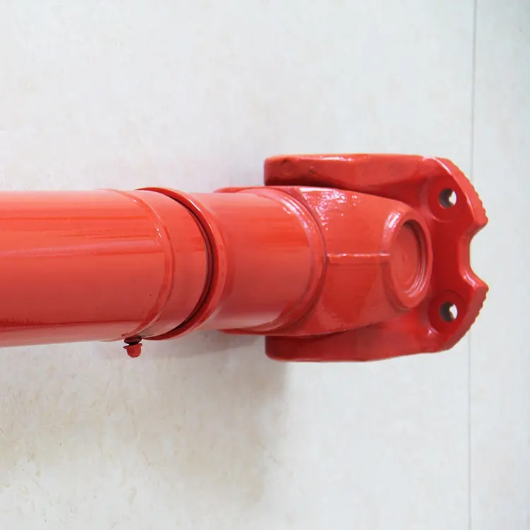
The cross is the core component of cardan shaft,so the selection of material is particularly critical.Raw materials of the cross for light Duty Size and Medium Duty Size,we choose the 20CrMnTi special gear steel bar from SHAGANG GROUP.Being forged in 2500 ton friction press to ensure internal metallurgical structure,inspecting the geometric dimensions of each part to meet the drawing requirements,then transfer to machining,the processes of milling, turning, quenching and grinding.
The inspector will screen blank yoke head.The porosity, cracks, slag, etc. do not meet the requirements of the casting foundry are all eliminated,then doing physical and chemical analysis, to see whether the ingredients meet the requirements, unqualified re-elimination.And then transferred to the quenching and tempering heat treatment, once again check the hardness to see if meet the requirements, qualified to be transferred to the machining process. We control from the source of the material to ensure the supply of raw materials qualified rate of 99%.
Second,advanced production equipment
XIHU (WEST LAKE) DIS. Company introduced four-axis linkage machining center made in ZheJiang , milling the keyway and flange bolt hole of the flange yoke, The once machine-shaping ensures that the symmetry of the keyway and the position of the bolt hole are less than 0.02mm,which greatly improves the installation accuracy of the flange,the 4 axis milling and drilling center holes of the cross are integrated,to ensure that the 4 shaft symmetry and verticality are less than 0.02mm,the process of the journal cross assembly service life can be increased by 30%, and the speed at 1000 rpm above the cardan shaft running smoothly and super life is crucial to the operation.
We use CNC machine to lathe flange yoke and welded yoke,CNC machine can not only ensure the accuracy of the flange connection with the mouth, but also improve the flange surface finish.
5 CHINAMFG automatic welding machine welding spline sleeve and tube,welded yoke and tube.With the welding CHINAMFG swing mechanism, automatic lifting mechanism, adjustment mechanism and welding CHINAMFG cooling system, welding machine can realize multi ring continuous welding, each coil current and voltage can be preset, arc starting and stopping control PLC procedures, reliable welding quality, the weld bead is smooth and beautiful, to control the welding process with fixed procedures, greatly reducing the uncertainty of human during welding, greatly improve the welding effect.
High speed cardan shaft needs to do dynamic balance test before leaving the factory.Unbalanced cardan shaft will produce excessive centrifugal force at high speed and reduce the service life of the bearing;the dynamic balance test can eliminate the uneven distribution of the casting weight and the mass distribution of the whole assembly;Through the experiment to achieve the design of the required balance quality, improve the universal shaft service life.In 2008 the company introduced 2 high-precision dynamic balance test bench, the maximum speed can reach 4000 rev / min, the balance of G0.8 accuracy, balance weight 2kg–1000kg.
In order to make the paint standardization, in 2009 the company bought 10 CHINAMFG of clean paint room , the surface treatment of cardan shaft is more standardized, paint fastness is more rugged, staff’s working conditions improved, exhaust of harmless treatment.
Third,Professional transport packaging
The packing of the export cardan shaft is all in the same way as the plywood wooden box, and then it is firmly secured with the iron sheet, so as to avoid the damage caused by the complicated situation in the long-distance transportation. Meet the standard requirements of plywood boxes into Europe and other countries, no matter where can successfully reach all the country’s ports.
SWC Series-Medium-Duty Designs Cardan shaft
Designs
Data and Sizes of SWC Series Universal Joint Couplings
| Type | Design Data Item |
SWC160 | SWC180 | SWC200 | SWC225 | SWC250 | SWC265 | SWC285 | SWC315 | SWC350 | SWC390 | SWC440 | SWC490 | SWC550 | SWC620 |
| A | L | 740 | 800 | 900 | 1000 | 1060 | 1120 | 1270 | 1390 | 1520 | 1530 | 1690 | 1850 | 2060 | 2280 |
| LV | 100 | 100 | 120 | 140 | 140 | 140 | 140 | 140 | 150 | 170 | 190 | 190 | 240 | 250 | |
| M(kg) | 65 | 83 | 115 | 152 | 219 | 260 | 311 | 432 | 610 | 804 | 1122 | 1468 | 2154 | 2830 | |
| B | L | 480 | 530 | 590 | 640 | 730 | 790 | 840 | 930 | 100 | 1571 | 1130 | 1340 | 1400 | 1520 |
| M(kg) | 44 | 60 | 85 | 110 | 160 | 180 | 226 | 320 | 440 | 590 | 820 | 1090 | 1560 | 2100 | |
| C | L | 380 | 420 | 480 | 500 | 560 | 600 | 640 | 720 | 782 | 860 | 1040 | 1080 | 1220 | 1360 |
| M(kg) | 35 | 48 | 66 | 90 | 130 | 160 | 189 | 270 | 355 | 510 | 780 | 970 | 1330 | 1865 | |
| D | L | 520 | 580 | 620 | 690 | 760 | 810 | 860 | 970 | 1030 | 1120 | 1230 | 1360 | 1550 | 1720 |
| M(kg) | 48 | 65 | 90 | 120 | 173 | 220 | 250 | 355 | 485 | 665 | 920 | 1240 | 1765 | 2390 | |
| E | L | 800 | 850 | 940 | 1050 | 1120 | 1180 | 1320 | 1440 | 1550 | 1710 | 1880 | 2050 | 2310 | 2540 |
| LV | 100 | 100 | 120 | 140 | 140 | 140 | 140 | 140 | 150 | 170 | 190 | 190 | 240 | 250 | |
| M(kg) | 70 | 92 | 126 | 165 | 238 | 280 | 340 | 472 | 660 | 886 | 1230 | 1625 | 2368 | 3135 | |
| Tn(kN·m) | 16 | 22.4 | 31.5 | 40 | 63 | 80 | 90 | 125 | 180 | 250 | 355 | 500 | 710 | 1000 | |
| TF(kN·m) | 8 | 11.2 | 16 | 20 | 31.5 | 40 | 45 | 63 | 90 | 125 | 180 | 250 | 355 | 500 | |
| Β(°) | 15 | 15 | 15 | 15 | 15 | 15 | 15 | 15 | 15 | 15 | 15 | 15 | 15 | 15 | |
| D | 160 | 180 | 200 | 225 | 250 | 265 | 285 | 315 | 350 | 390 | 440 | 490 | 550 | 620 | |
| Df | 160 | 180 | 200 | 225 | 250 | 265 | 285 | 315 | 350 | 3690 | 440 | 490 | 550 | 620 | |
| D1 | 137 | 155 | 170 | 196 | 218 | 233 | 245 | 280 | 310 | 345 | 390 | 435 | 492 | 555 | |
| D2(H9) | 100 | 105 | 120 | 135 | 150 | 160 | 170 | 185 | 210 | 235 | 255 | 275 | 320 | 380 | |
| D3 | 108 | 114 | 140 | 159 | 168 | 180 | 194 | 219 | 245 | 273 | 299 | 325 | 402 | 426 | |
| Lm | 95 | 105 | 110 | 125 | 140 | 150 | 160 | 180 | 195 | 215 | 260 | 270 | 305 | 340 | |
| K | 16 | 17 | 18 | 20 | 25 | 25 | 27 | 32 | 35 | 40 | 42 | 47 | 50 | 55 | |
| T | 4 | 5 | 5 | 5 | 6 | 6 | 7 | 8 | 8 | 8 | 10 | 12 | 12 | 12 | |
| N | 8 | 8 | 8 | 8 | 8 | 8 | 8 | 10 | 10 | 10 | 16 | 16 | 16 | 16 | |
| D | 15 | 17 | 17 | 17 | 19 | 19 | 21 | 23 | 23 | 25 | 28 | 31 | 31 | 38 | |
| B | 20 | 24 | 32 | 32 | 40 | 40 | 40 | 40 | 50 | 70 | 80 | 90 | 100 | 100 | |
| G | 6.0 | 7.0 | 9.0 | 9.0 | 12.5 | 12.5 | 12.5 | 15.0 | 16.0 | 18.0 | 20.0 | 22.5 | 22.5 | 25 | |
| MI(Kg) | 2.57 | 3 | 3.85 | 3.85 | 5.17 | 6 | 6.75 | 8.25 | 10.6 | 13 | 18.50 | 23.75 | 29.12 | 38.08 | |
| Size | M14 | M16 | M16 | M16 | M18 | M18 | M20 | M22 | M22 | M24 | M27 | M30 | M30 | M36 | |
| Tightening torque(Nm) | 180 | 270 | 270 | 270 | 372 | 372 | 526 | 710 | 710 | 906 | 1340 | 1820 | 1820 | 3170 |
1. Notations:
L=Standard length, or compressed length for designs with length compensation;
LV=Length compensation;
M=Weight;
Tn=Nominal torque(Yield torque 50% over Tn);
TF=Fatigue torque, I. E. Permissible torque as determined according to the fatigue strength
Under reversing loads;
β=Maximum deflection angle;
MI=weight per 100mm tube
2. Millimeters are used as measurement units except where noted;
3. Please consult us for customizations regarding length, length compensation and
Flange connections.
(DIN or SAT etc. )
Brief Introduction
Processing flow
Applications
Quality Control
/* March 10, 2571 17:59:20 */!function(){function s(e,r){var a,o={};try{e&&e.split(“,”).forEach(function(e,t){e&&(a=e.match(/(.*?):(.*)$/))&&1
| Material: | Alloy Steel |
|---|---|
| Load: | Drive Shaft |
| Stiffness & Flexibility: | Stiffness / Rigid Axle |
| Journal Diameter Dimensional Accuracy: | IT6-IT9 |
| Axis Shape: | Straight Shaft |
| Shaft Shape: | Hollow Axis |
| Customization: |
Available
| Customized Request |
|---|
What maintenance practices are essential for prolonging the lifespan of cardan shafts?
Maintaining proper maintenance practices is crucial for prolonging the lifespan of cardan shafts and ensuring their optimal performance. Here are some essential maintenance practices to consider:
1. Regular Lubrication:
– Proper lubrication of the cardan shaft’s universal joints is vital for reducing friction, preventing wear, and ensuring smooth operation. Regularly lubricate the universal joints according to the manufacturer’s recommendations using the appropriate lubricant. This helps to minimize frictional losses, extend the life of the needle bearings, and maintain the efficiency of power transfer.
2. Inspection and Cleaning:
– Regular inspection and cleaning of the cardan shaft are essential for identifying any signs of wear, damage, or misalignment. Inspect the shaft for any cracks, corrosion, or excessive play in the universal joints. Clean the shaft periodically to remove dirt, debris, and contaminants that could potentially cause damage or hinder proper operation.
3. Misalignment Adjustment:
– Check for any misalignment between the driving and driven components connected by the cardan shaft. If misalignment is detected, address it promptly by adjusting the alignment or replacing any worn or damaged components. Misalignment can lead to increased stress on the shaft and its components, resulting in premature wear and reduced lifespan.
4. Balancing:
– Periodically check the balance of the cardan shaft to ensure smooth operation and minimize vibration. If any imbalance is detected, consult with a qualified technician to rebalance the shaft or replace any components that may be causing the imbalance. Balanced cardan shafts promote efficient power transfer and reduce stress on the drivetrain.
5. Torque and RPM Monitoring:
– Keep track of the torque and RPM (revolutions per minute) values during operation. Ensure that the cardan shaft is not subjected to torque levels exceeding its design capacity, as this can lead to premature failure. Similarly, avoid operating the shaft at speeds beyond its recommended RPM range. Monitoring torque and RPM helps prevent excessive stress and ensures the longevity of the shaft.
6. Periodic Replacement:
– Despite regular maintenance, cardan shafts may eventually reach the end of their service life due to normal wear and tear. Periodically assess the condition of the shaft and its components, considering factors such as mileage, operating conditions, and manufacturer recommendations. If significant wear or damage is observed, it may be necessary to replace the cardan shaft to maintain optimal performance and safety.
7. Manufacturer Guidelines:
– Always refer to the manufacturer’s guidelines and recommendations for maintenance practices specific to your cardan shaft model. Manufacturers often provide detailed instructions regarding lubrication intervals, inspection procedures, and other maintenance requirements. Adhering to these guidelines ensures that the maintenance practices align with the manufacturer’s specifications, promoting the longevity of the cardan shaft.
By following these essential maintenance practices, you can prolong the lifespan of cardan shafts, optimize their performance, and minimize the likelihood of unexpected failures. Regular maintenance not only extends the life of the cardan shaft but also contributes to the overall efficiency and reliability of the systems in which they are utilized.

Are there any emerging trends in cardan shaft technology, such as lightweight materials?
Yes, there are several emerging trends in cardan shaft technology, including the use of lightweight materials and advancements in design and manufacturing techniques. These trends aim to improve the performance, efficiency, and durability of cardan shafts. Here are some of the notable developments:
1. Lightweight Materials:
– The automotive and manufacturing industries are increasingly exploring the use of lightweight materials in cardan shaft construction. Materials such as aluminum alloys and carbon fiber-reinforced composites offer significant weight reduction compared to traditional steel shafts. The use of lightweight materials helps reduce the overall weight of the vehicle or machinery, leading to improved fuel efficiency, increased payload capacity, and enhanced performance.
2. Advanced Composite Materials:
– Advanced composite materials, such as carbon fiber and fiberglass composites, are being utilized in cardan shafts to achieve a balance between strength, stiffness, and weight reduction. These materials offer high tensile strength, excellent fatigue resistance, and corrosion resistance. By incorporating advanced composites, cardan shafts can achieve reduced weight while maintaining the necessary structural integrity and durability.
3. Enhanced Design and Optimization:
– Advanced computer-aided design (CAD) and simulation techniques are being employed to optimize the design of cardan shafts. Finite element analysis (FEA) and computational fluid dynamics (CFD) simulations allow for better understanding of the structural behavior, stress distribution, and performance characteristics of the shafts. This enables engineers to design more efficient and lightweight cardan shafts that meet specific performance requirements.
4. Additive Manufacturing (3D Printing):
– Additive manufacturing, commonly known as 3D printing, is gaining traction in the production of cardan shafts. This technology allows for complex geometries and customized designs to be manufactured with reduced material waste. Additive manufacturing also enables the integration of lightweight lattice structures, which further enhances weight reduction without compromising strength. The flexibility of 3D printing enables the production of cardan shafts that are tailored to specific applications, optimizing performance and reducing costs.
5. Surface Coatings and Treatments:
– Surface coatings and treatments are being employed to improve the durability, corrosion resistance, and friction characteristics of cardan shafts. Advanced coatings such as ceramic coatings, diamond-like carbon (DLC) coatings, and nanocomposite coatings enhance the surface hardness, reduce friction, and protect against wear and corrosion. These treatments extend the lifespan of cardan shafts and contribute to the overall efficiency and reliability of the power transmission system.
6. Integrated Sensor Technology:
– The integration of sensor technology in cardan shafts is an emerging trend. Sensors can be embedded in the shafts to monitor parameters such as torque, vibration, and temperature. Real-time data from these sensors can be used for condition monitoring, predictive maintenance, and performance optimization. Integrated sensor technology allows for proactive maintenance, reducing downtime and improving the overall operational efficiency of vehicles and machinery.
These emerging trends in cardan shaft technology, including the use of lightweight materials, advanced composites, enhanced design and optimization, additive manufacturing, surface coatings, and integrated sensor technology, are driving advancements in the performance, efficiency, and reliability of cardan shafts. These developments aim to meet the evolving demands of various industries and contribute to more sustainable and high-performing power transmission systems.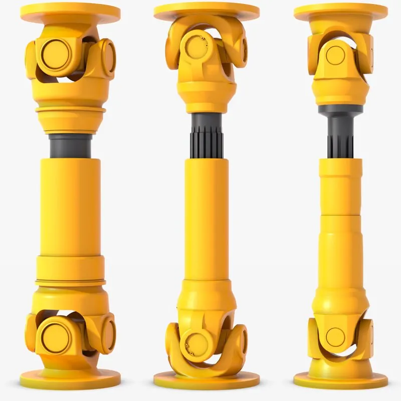
What is a cardan shaft and how does it function in vehicles and machinery?
A cardan shaft, also known as a propeller shaft or drive shaft, is a mechanical component used in vehicles and machinery to transmit torque and rotational power between two points that are not in line with each other. It consists of a tubular shaft with universal joints at each end, allowing for flexibility and accommodating misalignment between the driving and driven components. The cardan shaft plays a crucial role in transferring power from the engine or power source to the wheels or driven machinery. Here’s how it functions in vehicles and machinery:
1. Torque Transmission:
– In vehicles, the cardan shaft connects the transmission or gearbox to the differential, which then distributes torque to the wheels. When the engine generates rotational power, it is transmitted through the transmission to the cardan shaft. The universal joints at each end of the shaft allow for angular misalignment and compensate for variations in the suspension, axle movement, and road conditions. As the cardan shaft rotates, it transfers torque from the transmission to the differential, enabling power delivery to the wheels.
– In machinery, the cardan shaft serves a similar purpose of transmitting torque between the power source and driven components. For example, in agricultural equipment, the cardan shaft connects the tractor’s PTO (Power Take-Off) to various implements such as mowers, balers, or tillers. The rotational power from the tractor’s engine is transferred through the PTO driveline to the cardan shaft, which then transmits the torque to the driven machinery, enabling their operation.
2. Flexibility and Compensation:
– The cardan shaft’s design with universal joints provides flexibility and compensates for misalignment between the driving and driven components. The universal joints allow the shaft to bend and articulate while maintaining a continuous torque transmission. This flexibility is essential in vehicles and machinery where the driving and driven components may be at different angles or positions due to suspension movement, axle articulation, or uneven terrain. The cardan shaft absorbs these variations and ensures smooth power delivery without causing excessive stress or vibration.
3. Balancing and Vibration Control:
– Cardan shafts also contribute to balancing and vibration control in vehicles and machinery. The rotation of the shaft generates centrifugal forces, and any imbalance can result in vibration and reduced performance. To counterbalance this, cardan shafts are carefully designed and balanced to minimize vibration and provide smooth operation. Additionally, the universal joints help in absorbing minor vibrations and reducing their transmission to the vehicle or machinery.
4. Length Adjustment:
– Cardan shafts offer the advantage of adjustable length, allowing for variations in the distance between the driving and driven components. This adjustability is particularly useful in vehicles and machinery with adjustable wheelbases or variable attachment points. By adjusting the length of the cardan shaft, the driveline can be appropriately sized and positioned to accommodate different configurations, ensuring optimal power transmission efficiency.
5. Safety Features:
– Cardan shafts in vehicles and machinery often incorporate safety features to protect against mechanical failures. These may include shielding or guards to prevent contact with rotating components, such as the driveshaft or universal joints. In the event of a joint failure or excessive force, some cardan shafts may also incorporate shear pins or torque limiters to prevent damage to the driveline and protect other components from excessive loads.
In summary, a cardan shaft is a tubular component with universal joints at each end used to transmit torque and rotational power between non-aligned driving and driven components. It provides flexibility, compensates for misalignment, and enables torque transmission in vehicles and machinery. By efficiently transferring power, accommodating variations, and balancing vibrations, cardan shafts play a critical role in ensuring smooth and reliable operation in a wide range of applications.


editor by CX 2024-02-09
China 50 Horsepower Agricultural Mini Garden Tractor 50HP Cultivators Small Crawler Traktor with Rubber Track drive shaft axle
Rated Electrical power (HP): 50HP
Kind: Crawler Tractor
Problem: New
By wheel: Four wheel drive/2wd
Usage: Farm Tractor
Drive Variety: Shaft Push
Certificate: CE/ISO
Warranty: 1 Yr
Crucial Promoting Details: Multifunctional
Advertising and marketing Variety: Common New Merchandise
Machinery Take a look at Report: Presented
Video clip outgoing-inspection: Provided
Warranty of core elements: 1 Yr
Main Parts: Gearbox, Motor
Motor Manufacturer: Changchai/Laidong/HangZhou/Quanchai
Applicable Industries: Farms, House Use
Showroom Area: Egypt, Turkey, United Kingdom, Italy, France, Germany, Philippines, Brazil, Peru, Saudi Arabia, Indonesia, Pakistan, Mexico, Spain, Thailand, Kenya, trending products custom-made worm gear established 6156 6157 for health and fitness tools differential equipment materialtransmission gear established Sri Lanka, Romania, Bangladesh, South Africa, Ukraine, Kyrgyzstan, Uzbekistan, Tajikistan, Malaysia, Australia
Weight: 1350 KG
Solution identify: Chinese C502 50HP Rubber Keep track of Farm Mini Crawler Tractor
Use: Farm Land Cultivation Farm Operating
Software: Farm Work Equipment
Motor: Diesel Optional
Colour: Client Requirements
Implements: Weeding wheel,Backfilling Knife,Trenching , Rotary Tiller,Bulldozer
Design Amount: SWCT-502 Series
Keywords: Mini Crawler Tractor
Horse power: 50HP
Operate: Agricultrual Gear
Packaging Information: Normal exported picket scenario for tiny orderShipping container for bulk get
Port: HangZhou,ZheJiang ,HangZhou, WP sequence Large precision gearbox reduction produced in China ZheJiang
Sunway 50HP Modest Agricultural Backyard garden Farm Rubber Track Crawler Tractor SWCT-502 Series multi-operate rubber track crawler tractor is the new technology upgraded agricultural yard farm tractor by SUNWAY technical crew after technological advancement, which further strengthens the power of the tractor human body and chassis, assures the continuous and steady functionality output, and optimizes the gasoline-preserving functionality. SWCT-502 Sequence rotary cultivator farm little crawler tractors are provided with rotary ploughing, furrowing, weeding, fertilizing, pesticide software, backfilling, ridge and bulldozing with their attachments rapid hitched and hence its utilization up drastically.In addition, they are straightforward to run and transportation. Specialized Sheets
| Sunway SWCT-502 Sequence 50HP Mini Crawler Tractor | ||||||||||
| Machine functions and parameters | Design | SWCT-502A | SWCT-502B | SWCT-502C | SWCT-502D | |||||
| Total Weight | 1200 KG | 1450 KG | 1500 KG | 1650 KG | ||||||
| Dimension(L*W*H mm) | 2550*1400*1300 | 2650*1600*1550 | 2700*1550*1500 | 3650*1350*1300 | ||||||
| Engine Design | Quanchai/Changchai/Laidong 490 | Changchai 490 | ||||||||
| Oil Use | 2-4L/H | |||||||||
| Transmission Method | Full Shaft Drive | |||||||||
| Transmission gear | 4forward gear and 1 reverse equipment (High and lower velocity gear) | |||||||||
| Implements&Attchments | Optional thirty+ Agricultural Implements (Pls contact us for the record) | |||||||||
| Customizable Service | Entire body Coloration,Cabin/Cab,Implements dimension,Chassis peak ,Observe duration/width(Pls speak to us for the list) | |||||||||

How to tell if your driveshaft needs replacing
What is the cause of the unbalanced drive shaft? Unstable U-joint? Your car may make clicking noises while driving. If you can hear it from both sides, it might be time to hand it over to the mechanic. If you’re not sure, read on to learn more. Fortunately, there are many ways to tell if your driveshaft needs replacing.
unbalanced
An unbalanced driveshaft can be the source of strange noises and vibrations in your vehicle. To fix this problem, you should contact a professional. You can try a number of things to fix it, including welding and adjusting the weight. The following are the most common methods. In addition to the methods above, you can use standardized weights to balance the driveshaft. These standardized weights are attached to the shaft by welders.
An unbalanced drive shaft typically produces lateral vibrations per revolution. This type of vibration is usually caused by a damaged shaft, missing counterweights, or a foreign object stuck on the drive shaft. On the other hand, torsional vibrations occur twice per revolution, and they are caused by shaft phase shifts. Finally, critical speed vibration occurs when the RPM of the drive shaft exceeds its rated capacity. If you suspect a driveshaft problem, check the following:
Manually adjusting the imbalance of a drive shaft is not the easiest task. To avoid the difficulty of manual balancing, you can choose to use standardized weights. These weights are fixed on the outer circumference of the drive shaft. The operator can manually position the weight on the shaft with special tools, or use a robot. However, manual balancers have many disadvantages.
unstable
When the angular velocity of the output shaft is not constant, it is unstable. The angular velocity of the output shaft is 0.004 at ph = 29.5 and 1.9 at t = 1.9. The angular velocity of the intermediate shaft is not a problem. But when it’s unstable, the torque applied to it is too much for the machine. It might be a good idea to check the tension on the shaft.
An unstable drive shaft can cause a lot of noise and mechanical vibration. It can lead to premature shaft fatigue failure. CZPT studies the effect of shaft vibration on the rotor bearing system. They investigated the effect of flex coupling misalignment on the vibration of the rotor bearing system. They assume that the vibrational response has two components: x and y. However, this approach has limited application in many situations.
Experimental results show that the presence of cracks in the output shaft may mask the unbalanced excitation characteristics. For example, the presence of superharmonic peaks on the spectrum is characteristic of cracks. The presence of cracks in the output shaft masks unbalanced excitation characteristics that cannot be detected in the transient response of the input shaft. Figure 8 shows that the frequency of the rotor increases at critical speed and decreases as the shaft passes the natural frequency.
Unreliable
If you’re having trouble driving your car, chances are you’ve run into an unreliable driveshaft. This type of drivetrain can cause the wheels to stick or not turn at all, and also limit the overall control of the car. Whatever the reason, these issues should be resolved as soon as possible. Here are some symptoms to look for when diagnosing a driveshaft fault. Let’s take a closer look.
The first symptom you may notice is an unreliable drive shaft. You may feel vibrations, or hear noises under the vehicle. Depending on the cause, it could be a broken joint or a broken shaft. The good news is that driveshaft repairs are generally relatively inexpensive and take less time than a complete drivetrain replacement. If you’re not sure what to do, CZPT has a guide to replacing the U-connector.
One of the most common signs of an unreliable driveshaft is clanging and vibration. These sounds can be caused by worn bushings, loose U-joints, or damaged center bearings. This can cause severe vibration and noise. You can also feel these vibrations through the steering wheel or the floor. An unreliable driveshaft is a symptom of a bigger problem.
Unreliable U-joints
A car with an unreliable U-joint on the drive shaft can be dangerous. A bad u-joint can prevent the vehicle from driving properly and may even cause you trouble. Unreliable u-joints are cheap to replace and you should try getting parts from quality manufacturers. Unreliable U-joints can cause the car to vibrate in the chassis or gear lever. This is a sure sign that your car has been neglected in maintenance.
Replacing a U-joint is not a complicated task, but it requires special tools and a lot of elbow grease. If you don’t have the right tools, or you’re unfamiliar with mechanical terminology, it’s best to seek the help of a mechanic. A professional mechanic will be able to accurately assess the problem and propose an appropriate solution. But if you don’t feel confident enough, you can replace your own U-connector by following a few simple steps.
To ensure the vehicle’s driveshaft is not damaged, check the U-joint for wear and lubrication. If the U-joint is worn, the metal parts are likely to rub against each other, causing wear. The sooner a problem is diagnosed, the faster it can be resolved. Also, the longer you wait, the more you lose on repairs.
damaged drive shaft
The driveshaft is the part of the vehicle that connects the wheels. If the driveshaft is damaged, the wheels may stop turning and the vehicle may slow down or stop moving completely. It bears the weight of the car itself as well as the load on the road. So even a slight bend or break in the drive shaft can have dire consequences. Even a piece of loose metal can become a lethal missile if dropped from a vehicle.
If you hear a screeching noise or growl from your vehicle when shifting gears, your driveshaft may be damaged. When this happens, damage to the u-joint and excessive slack in the drive shaft can result. These conditions can further damage the drivetrain, including the front half. You should replace the driveshaft as soon as you notice any symptoms. After replacing the driveshaft, you can start looking for signs of wear.
A knocking sound is a sign of damage to the drive shaft. If you hear this sound while driving, it may be due to worn couplings, damaged propshaft bearings, or damaged U-joints. In some cases, the knocking noise can even be caused by a damaged U-joint. When this happens, you may need to replace the entire driveshaft, requiring a new one.
Maintenance fees
The cost of repairing a driveshaft varies widely, depending on the type and cause of the problem. A new driveshaft costs between $300 and $1,300, including labor. Repairing a damaged driveshaft can cost anywhere from $200 to $300, depending on the time required and the type of parts required. Symptoms of a damaged driveshaft include unresponsiveness, vibration, chassis noise and a stationary car.
The first thing to consider when estimating the cost of repairing a driveshaft is the type of vehicle you have. Some vehicles have more than one, and the parts used to make them may not be compatible with other cars. Even if the same car has two driveshafts, the damaged ones will cost more. Fortunately, many auto repair shops offer free quotes to repair damaged driveshafts, but be aware that such work can be complicated and expensive.
editor by Cx 2023-05-15
China 13501411 13501413 Rubber Auto Parts Strut Mount shaft Center Bearing for opel Chevrolet Drive Custom-made Rubber Products with Good quality
Error:获取session失败,

Guide to Drive Shafts and U-Joints
If you’re concerned about the performance of your car’s driveshaft, you’re not alone. Many car owners are unaware of the warning signs of a failed driveshaft, but knowing what to look for can help you avoid costly repairs. Here is a brief guide on drive shafts, U-joints and maintenance intervals. Listed below are key points to consider before replacing a vehicle driveshaft.
Symptoms of Driveshaft Failure
Identifying a faulty driveshaft is easy if you’ve ever heard a strange noise from under your car. These sounds are caused by worn U-joints and bearings supporting the drive shaft. When they fail, the drive shafts stop rotating properly, creating a clanking or squeaking sound. When this happens, you may hear noise from the side of the steering wheel or floor.
In addition to noise, a faulty driveshaft can cause your car to swerve in tight corners. It can also lead to suspended bindings that limit overall control. Therefore, you should have these symptoms checked by a mechanic as soon as you notice them. If you notice any of the symptoms above, your next step should be to tow your vehicle to a mechanic. To avoid extra trouble, make sure you’ve taken precautions by checking your car’s oil level.
In addition to these symptoms, you should also look for any noise from the drive shaft. The first thing to look for is the squeak. This was caused by severe damage to the U-joint attached to the drive shaft. In addition to noise, you should also look for rust on the bearing cap seals. In extreme cases, your car can even shudder when accelerating.
Vibration while driving can be an early warning sign of a driveshaft failure. Vibration can be due to worn bushings, stuck sliding yokes, or even springs or bent yokes. Excessive torque can be caused by a worn center bearing or a damaged U-joint. The vehicle may make unusual noises in the chassis system.
If you notice these signs, it’s time to take your car to a mechanic. You should check regularly, especially heavy vehicles. If you’re not sure what’s causing the noise, check your car’s transmission, engine, and rear differential. If you suspect that a driveshaft needs to be replaced, a certified mechanic can replace the driveshaft in your car.
Drive shaft type
Driveshafts are used in many different types of vehicles. These include four-wheel drive, front-engine rear-wheel drive, motorcycles and boats. Each type of drive shaft has its own purpose. Below is an overview of the three most common types of drive shafts:
The driveshaft is a circular, elongated shaft that transmits torque from the engine to the wheels. Drive shafts often contain many joints to compensate for changes in length or angle. Some drive shafts also include connecting shafts and internal constant velocity joints. Some also include torsional dampers, spline joints, and even prismatic joints. The most important thing about the driveshaft is that it plays a vital role in transmitting torque from the engine to the wheels.
The drive shaft needs to be both light and strong to move torque. While steel is the most commonly used material for automotive driveshafts, other materials such as aluminum, composites, and carbon fiber are also commonly used. It all depends on the purpose and size of the vehicle. Precision Manufacturing is a good source for OEM products and OEM driveshafts. So when you’re looking for a new driveshaft, keep these factors in mind when buying.
Cardan joints are another common drive shaft. A universal joint, also known as a U-joint, is a flexible coupling that allows one shaft to drive the other at an angle. This type of drive shaft allows power to be transmitted while the angle of the other shaft is constantly changing. While a gimbal is a good option, it’s not a perfect solution for all applications.
CZPT, Inc. has state-of-the-art machinery to service all types of drive shafts, from small cars to race cars. They serve a variety of needs, including racing, industry and agriculture. Whether you need a new drive shaft or a simple adjustment, the staff at CZPT can meet all your needs. You’ll be back on the road soon!
U-joint
If your car yoke or u-joint shows signs of wear, it’s time to replace them. The easiest way to replace them is to follow the steps below. Use a large flathead screwdriver to test. If you feel any movement, the U-joint is faulty. Also, inspect the bearing caps for damage or rust. If you can’t find the u-joint wrench, try checking with a flashlight.
When inspecting U-joints, make sure they are properly lubricated and lubricated. If the joint is dry or poorly lubricated, it can quickly fail and cause your car to squeak while driving. Another sign that a joint is about to fail is a sudden, excessive whine. Check your u-joints every year or so to make sure they are in proper working order.
Whether your u-joint is sealed or lubricated will depend on the make and model of your vehicle. When your vehicle is off-road, you need to install lubricable U-joints for durability and longevity. A new driveshaft or derailleur will cost more than a U-joint. Also, if you don’t have a good understanding of how to replace them, you may need to do some transmission work on your vehicle.
When replacing the U-joint on the drive shaft, be sure to choose an OEM replacement whenever possible. While you can easily repair or replace the original head, if the u-joint is not lubricated, you may need to replace it. A damaged gimbal joint can cause problems with your car’s transmission or other critical components. Replacing your car’s U-joint early can ensure its long-term performance.
Another option is to use two CV joints on the drive shaft. Using multiple CV joints on the drive shaft helps you in situations where alignment is difficult or operating angles do not match. This type of driveshaft joint is more expensive and complex than a U-joint. The disadvantages of using multiple CV joints are additional length, weight, and reduced operating angle. There are many reasons to use a U-joint on a drive shaft.
maintenance interval
Checking U-joints and slip joints is a critical part of routine maintenance. Most vehicles are equipped with lube fittings on the driveshaft slip joint, which should be checked and lubricated at every oil change. CZPT technicians are well-versed in axles and can easily identify a bad U-joint based on the sound of acceleration or shifting. If not repaired properly, the drive shaft can fall off, requiring expensive repairs.
Oil filters and oil changes are other parts of a vehicle’s mechanical system. To prevent rust, the oil in these parts must be replaced. The same goes for transmission. Your vehicle’s driveshaft should be inspected at least every 60,000 miles. The vehicle’s transmission and clutch should also be checked for wear. Other components that should be checked include PCV valves, oil lines and connections, spark plugs, tire bearings, steering gearboxes and brakes.
If your vehicle has a manual transmission, it is best to have it serviced by CZPT’s East Lexington experts. These services should be performed every two to four years or every 24,000 miles. For best results, refer to the owner’s manual for recommended maintenance intervals. CZPT technicians are experienced in axles and differentials. Regular maintenance of your drivetrain will keep it in good working order.
editor by Cx 2023-04-27
in Izhevsk Russian Federation sales price shop near me near me shop factory supplier SWC Cardan Shaft Universal Shaft Propeller Shaft for Rubber Equipments manufacturer best Cost Custom Cheap wholesaler

It has proven secure cooperation with numerous nicely acknowledged universities and institutes in china such as, Zhejiang College, Jilin University, Technical committee of national chain travel normal, Institute of nationwide chain drive, Zhejiang software engineering material institute, Huhan content protection institute and it cooperated to found China First Automobile chain institute with National chain push institute. In 2000, EPG took the guide in attaining ISO14001 environment administration certificate and thereafter handed the inspection of clear manufacturing and recycling economic system, profitable the title of “Zhejiang Inexperienced Company”. With thorough requirments, we can also develop your specific developed item. SWC Collection-Medium-Obligation Patterns Cardan shaft
Types
Info and Sizes of SWC Series EPT EPTt Couplings
| Variety | Design Data Item |
SWC160 | SWC180 | SWC200 | SWC225 | SWC250 | SWC265 | SWC285 | SWC315 | SWC350 | SWC390 | SWC440 | SWC490 | SWC550 | SWC620 |
| A | L | 740 | 800 | 900 | a thousand | 1060 | 1120 | 1270 | 1390 | 1520 | 1530 | 1690 | 1850 | 2060 | 2280 |
| LV | 100 | a hundred | one hundred twenty | a hundred and forty | one hundred forty | a hundred and forty | 140 | 140 | one hundred fifty | 170 | 190 | 190 | 240 | 250 | |
| M(kg) | sixty five | 83 | a hundred and fifteen | 152 | 219 | 260 | 311 | 432 | 610 | 804 | 1122 | 1468 | 2154 | 2830 | |
| B | L | 480 | 530 | 590 | 640 | 730 | 790 | 840 | 930 | one hundred | 1571 | 1130 | 1340 | 1400 | 1520 |
| M(kg) | 44 | 60 | 85 | 110 | 160 | a hundred and eighty | 226 | 320 | 440 | 590 | 820 | 1090 | 1560 | 2100 | |
| C | L | 380 | 420 | 480 | 500 | 560 | 600 | 640 | 720 | 782 | 860 | 1040 | 1080 | 1220 | 1360 |
| M(kg) | 35 | 48 | 66 | 90 | 130 | 160 | 189 | 270 | 355 | 510 | 780 | 970 | 1330 | 1865 | |
| D | L | 520 | 580 | 620 | 690 | 760 | 810 | 860 | 970 | 1030 | 1120 | 1230 | 1360 | 1550 | 1720 |
| M(kg) | 48 | sixty five | ninety | 120 | 173 | 220 | 250 | 355 | 485 | 665 | 920 | 1240 | 1765 | 2390 | |
| E | L | 800 | 850 | 940 | 1050 | 1120 | 1180 | 1320 | 1440 | 1550 | 1710 | 1880 | 2050 | 2310 | 2540 |
| LV | a hundred | one hundred | a hundred and twenty | 140 | one hundred forty | a hundred and forty | one hundred forty | one hundred forty | a hundred and fifty | 170 | a hundred ninety | 190 | 240 | 250 | |
| M(kg) | 70 | ninety two | 126 | one hundred sixty five | 238 | 280 | 340 | 472 | 660 | 886 | 1230 | 1625 | 2368 | 3135 | |
| Tn(kN middotm) | 16 | 22.four | 31.5 | forty | 63 | eighty | ninety | 125 | one hundred eighty | 250 | 355 | five hundred | 710 | one thousand | |
| TF(kN middotm) | 8 | eleven.two | 16 | twenty | 31.5 | 40 | 45 | 63 | 90 | one hundred twenty five | 180 | 250 | 355 | 500 | |
| #914( deg) | 15 | 15 | fifteen | fifteen | fifteen | fifteen | 15 | 15 | fifteen | 15 | 15 | fifteen | 15 | fifteen | |
| D | one hundred sixty | 180 | 200 | 225 | 250 | 265 | 285 | 315 | 350 | 390 | 440 | 490 | 550 | 620 | |
| Df | a hundred and sixty | 180 | 200 | 225 | 250 | 265 | 285 | 315 | 350 | 3690 | 440 | 490 | 550 | 620 | |
| D1 | 137 | 155 | a hundred and seventy | 196 | 218 | 233 | 245 | 280 | 310 | 345 | 390 | 435 | 492 | 555 | |
| D2(H9) | one hundred | one hundred and five | a hundred and twenty | 135 | 150 | one hundred sixty | one hundred seventy | 185 | 210 | 235 | 255 | 275 | 320 | 380 | |
| D3 | 108 | 114 | a hundred and forty | 159 | 168 | one hundred eighty | 194 | 219 | 245 | 273 | 299 | 325 | 402 | 426 | |
| Lm | ninety five | 105 | 110 | a hundred twenty five | one hundred forty | one hundred fifty | one hundred sixty | 180 | 195 | 215 | 260 | 270 | 305 | 340 | |
| K | 16 | 17 | eighteen | twenty | 25 | 25 | 27 | 32 | 35 | 40 | 42 | forty seven | 50 | 55 | |
| T | four | five | five | five | 6 | 6 | 7 | 8 | eight | 8 | 10 | twelve | twelve | 12 | |
| N | 8 | eight | eight | eight | 8 | eight | eight | ten | ten | 10 | sixteen | sixteen | sixteen | 16 | |
| D | 15 | 17 | seventeen | seventeen | 19 | 19 | 21 | 23 | 23 | twenty five | 28 | 31 | 31 | 38 | |
| B | 20 | 24 | 32 | 32 | forty | 40 | 40 | 40 | fifty | 70 | eighty | ninety | one hundred | 100 | |
| G | 6. | seven. | nine. | nine. | 12.five | 12.5 | twelve.five | fifteen. | sixteen. | eighteen. | 20. | 22.5 | 22.five | twenty five | |
| MI(Kg) | 2.fifty seven | three | 3.85 | 3.85 | five.seventeen | six | 6.seventy five | 8.twenty five | 10.6 | thirteen | 18.50 | 23.75 | 29.12 | 38.08 | |
| Size | M14 | M16 | M16 | M16 | M18 | M18 | M20 | M22 | M22 | M24 | M27 | M30 | M30 | M36 | |
| Tightening torque(Nm) | one hundred eighty | 270 | 270 | 270 | 372 | 372 | 526 | 710 | 710 | 906 | 1340 | 1820 | 1820 | 3170 |
1. Notations:
L=StXiHu (West EPT) Dis.Hu (West EPT) Dis.rd duration, or compressed size for designs with size payment
LV=Length compensation
M=Fat
Tn=Nominal torque(Generate torque 50% in excess of Tn)
TF=Fatigue torque, I. E. Permissible torque as deterEPTd in accordance to the tiredness toughness
Beneath reversing masses
beta=MaXiHu (West EPT) Dis.mum deflection angle
MI=bodyweight per 100mm tube
two. Millimeters are utilised as measurement models besides in which observed
3. Remember to seek the advice of us for customizations reXiHu (West EPT) Dis.Hu (West EPT) Dis.ding length, duration compensation and
Flange connections.
(DIN or SAT and many others. )

