Product Description
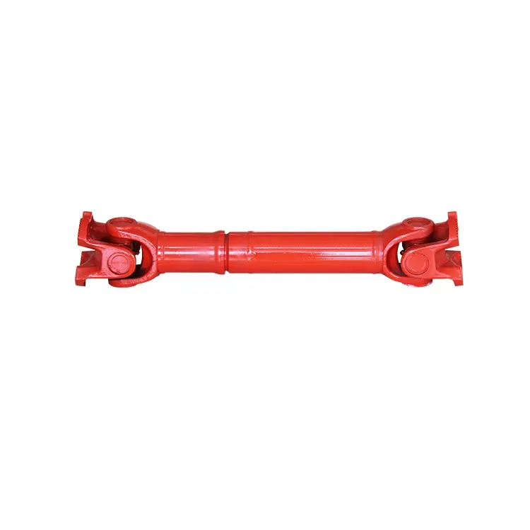
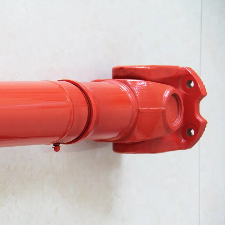
Widely Used SWC-WH Universal Coupling Without Flex Welding Type
Description:
SWC-WH without flexible welded universal coupling is a universal coupling used to connect 2 misaligned shafts. It consists of a pair of hinges located closely together, oriented at 90 ° to each other, and connected by a horizontal axis. The SWC-WH universal joint is not a constant velocity universal joint, but it can transmit power between shafts up to 25 °. The SWC-WH without a flexible welded universal coupling is a welded coupling, which means that 2 shafts are welded to the coupling. This makes it a more rigid coupling than flange couplings and more suitable for applications with high vibrations or impacts. It can be used in various applications, including rolling mills, lifting equipment, and other heavy machinery.
Advantages of SWC-WH non flexible welded universal coupling:
The following are some advantages of SWC-WH without flexible welded universal couplings:
Rigid coupling, capable of withstanding a large amount of vibration and impact. The welding structure of SWC-WH does not have a flexible welded universal coupling, making it very hard and helping to reduce vibration and impact transmission. This makes it a good choice for applications with high vibrations, such as in rolling mills and lifting equipment.
Universal couplings suitable for various applications. SWC-WH without flexible welded universal couplings can be used to connect shafts that deviate by 25 °. This makes it a universal coupling that can be used in various applications such as conveyor systems and machine tools.
Long service life. The welded structure of the coupling makes it very durable. SWC-WH without flexible welded universal couplings can also be lubricated to extend its service life.
The following are some drawbacks of SWC-WH without flexible welded universal couplings:
Not a constant velocity universal joint. The SWC-WH without a flexible welded universal joint is not a constant velocity universal joint, which means there will be some speed loss between the input and output shafts. In applications that require precise speed control, this may be a problem.
It is not as easy to disassemble as a flange coupling. The welding structure of SWC-WH does not have a flexible welded universal coupling, which makes it more difficult to disassemble than a flange coupling. If the coupling needs to be repaired or replaced, this may be a problem.
Overall, SWC-WH without flexible welded universal couplings is a reliable and durable coupling that is very suitable for various applications that require rigid couplings. However, it is not a constant velocity universal joint, and it may be more difficult to disassemble than a flange coupling.
SWC-WH non flexible welded universal coupling application:
The SWC-WH non flexible welded universal coupling is a universal coupling that can be used in various applications. Some of the most common applications include:
1. Conveyor system: SWC-WH without flexible welded universal coupling can be used to connect the transmission shaft to the conveyor belt in the conveyor system. This allows the conveyor belt to move smoothly and effectively, even when the drive shaft is not aligned with the conveyor belt.
2. Machine tool: SWC-WH without flexible welded universal coupling can be used to connect the motor to the spindle in the machine tool. In this way, even if the motor and spindle are not in a straight line, the spindle can rotate smoothly and accurately.
3. Rolling mill: SWC-WH without flexible welded universal coupling can be used to connect the transmission shaft to the rollers in the rolling mill. In this way, even if the drive shaft and the roller are not in a straight line, the roller can rotate smoothly and evenly.
4. Lifting equipment: In lifting equipment, SWC-WH without flexible welded universal coupling can be used to connect the motor to the lifting cable. This allows the lifting cable to move smoothly and effectively, even when the electric motor is not in line with the lifting cable.
5. Other heavy machinery: The SWC-WH non flexible welded universal coupling can be used for various other heavy machinery applications, such as agricultural machinery, engineering machinery, and mining machinery.
The SWC-WH non flexible welded universal coupling is a reliable and durable coupling that can provide years of trouble-free service. It is a good choice for applications that require rigid couplings and have significant vibrations or impacts.
Packing & shipping:
1 Prevent from damage.
2. As customers’ requirements, in perfect condition.
3. Delivery : As per contract delivery on time
4. Shipping : As per client request. We can accept CIF, Door to Door etc. or client authorized agent we supply all the necessary assistant.
FAQ:
Q 1: Are you a trading company or a manufacturer?
A: We are a professional manufacturer specializing in manufacturing various series of couplings.
Q 2:Can you do OEM?
Yes, we can. We can do OEM & ODM for all the customers with customized artworks in PDF or AI format.
Q 3:How long is your delivery time?
Generally, it is 20-30 days if the goods are not in stock. It is according to quantity.
Q 4: How long is your warranty?
A: Our Warranty is 12 months under normal circumstances.
Q 5: Do you have inspection procedures for coupling?
A:100% self-inspection before packing.
Q 6: Can I have a visit to your factory before the order?
A: Sure, welcome to visit our factory. /* January 22, 2571 19:08:37 */!function(){function s(e,r){var a,o={};try{e&&e.split(“,”).forEach(function(e,t){e&&(a=e.match(/(.*?):(.*)$/))&&1
| Standard Or Nonstandard: | Standard |
|---|---|
| Shaft Hole: | 19-32 |
| Torque: | >80N.M |
| Bore Diameter: | 19mm |
| Speed: | 4000r/M |
| Structure: | Rigid |
| Customization: |
Available
| Customized Request |
|---|
How do cardan shafts ensure efficient power transfer while maintaining balance?
Cardan shafts are designed to ensure efficient power transfer while maintaining balance between the driving and driven components. They employ various mechanisms and features that contribute to both aspects. Let’s explore how cardan shafts achieve efficient power transfer and balance:
1. Universal Joints:
– Cardan shafts utilize universal joints, also known as U-joints, to transmit torque from the driving component to the driven component. Universal joints consist of a cross-shaped yoke with needle bearings at each end. These needle bearings allow the joints to pivot and accommodate angular misalignment between the driving and driven components. By allowing for flexibility in movement, universal joints ensure efficient power transfer even when the components are not perfectly aligned, minimizing energy losses and maintaining balance.
2. Misalignment Compensation:
– Cardan shafts are designed to compensate for misalignment between the driving and driven components. The universal joints, along with slip yokes and telescopic sections, allow the shaft to adjust its length and accommodate variations in alignment. This misalignment compensation capability ensures that the cardan shaft can transmit power smoothly and efficiently, reducing stress on the components and maintaining balance during operation.
3. Balanced Design:
– Cardan shafts are engineered with a balanced design to minimize vibration and maintain smooth operation. The shaft tubes are typically symmetrically constructed, and the universal joints are positioned to distribute the mass evenly. This balanced design helps to reduce vibration and minimize the occurrence of unbalanced forces that can negatively impact power transfer and overall system performance. By maintaining balance, cardan shafts contribute to efficient power transmission and improve the lifespan of the components involved.
4. High-Quality Materials and Manufacturing:
– The materials used in the construction of cardan shafts, such as steel or aluminum alloy, are carefully selected for their strength, durability, and ability to maintain balance. High-quality materials ensure that the shafts can withstand the torque and operational stresses without deformation or failure, promoting efficient power transfer. Additionally, precise manufacturing processes and quality control measures are employed to ensure that the cardan shafts are accurately balanced during production, further enhancing their efficiency and balance.
5. Regular Maintenance and Inspection:
– To ensure continued efficient power transfer and balance, regular maintenance and inspection of cardan shafts are essential. This includes periodic lubrication of the universal joints, checking for wear or damage, and addressing any misalignment issues. Regular maintenance helps to preserve the balance of the shaft and ensures optimal performance and longevity.
Overall, cardan shafts ensure efficient power transfer while maintaining balance through the use of universal joints for torque transmission, misalignment compensation mechanisms, balanced design, high-quality materials, and regular maintenance. By incorporating these features, cardan shafts contribute to the smooth operation, reliability, and longevity of various applications in automotive, industrial, and other sectors that rely on efficient power transmission.
Can you provide real-world examples of vehicles and machinery that use cardan shafts?
Cardan shafts are widely used in various vehicles and machinery across different industries. They are employed in applications where torque transmission, power distribution, and flexibility are crucial. Here are some real-world examples of vehicles and machinery that utilize cardan shafts:
1. Automotive Vehicles:
– Cars, trucks, and SUVs: Cardan shafts are commonly found in rear-wheel drive (RWD) and four-wheel drive (4WD) vehicles. They connect the transmission or transfer case to the rear differential or front differential, respectively, enabling torque transmission to the wheels. Examples include sedans, pickup trucks, and SUVs like Jeep Wrangler, Ford F-150, and Toyota Land Cruiser.
– Buses and commercial vehicles: Cardan shafts are used in buses and commercial vehicles that have rear-wheel drive or all-wheel drive configurations. They transmit torque from the engine or transmission to the rear axle or multiple axles. Examples include city buses, coaches, and delivery trucks.
2. Off-Road and Utility Vehicles:
– Off-road vehicles: Many off-road vehicles, such as off-road trucks, SUVs, and all-terrain vehicles (ATVs) utilize cardan shafts. These shafts provide the necessary torque transfer and power distribution to all wheels for improved traction and off-road capabilities. Examples include the Land Rover Defender, Jeep Wrangler Rubicon, and Yamaha Grizzly ATV.
– Agricultural machinery: Farm equipment like tractors and combine harvesters often employ cardan shafts to transmit power from the engine to various attachments such as mowers, balers, and harvesters. The shafts enable efficient power distribution and flexibility for different agricultural tasks.
– Construction and mining machinery: Equipment used in construction and mining applications, such as excavators, loaders, and bulldozers, utilize cardan shafts to transfer power from the engine or transmission to the different components of the machinery. These shafts enable power distribution and torque transmission to various attachments, allowing for efficient operation in demanding environments.
3. Industrial Machinery:
– Manufacturing machinery: Cardan shafts are used in industrial equipment such as conveyors, mixers, and rotary equipment. They provide torque transmission and power distribution within the machinery, enabling efficient operation and movement of materials.
– Paper and pulp industry: Cardan shafts are employed in paper and pulp processing machinery, including paper machines and pulp digesters. These shafts facilitate power transmission and torque distribution to various parts of the machinery, contributing to smooth operation and high productivity.
– Steel and metal processing machinery: Equipment used in steel mills and metal processing facilities, such as rolling mills, extruders, and coil winding machines, often utilize cardan shafts. These shafts enable power transmission and torque distribution to the different components involved in metal forming, shaping, and processing.
These examples represent just a few of the many applications where cardan shafts are employed. Their versatility, durability, and ability to handle torque transmission and power distribution make them essential components in a wide range of vehicles and machinery across industries.

Can you explain the components and structure of a cardan shaft system?
A cardan shaft system, also known as a propeller shaft or drive shaft, consists of several components that work together to transmit torque and rotational power between non-aligned components. The structure of a cardan shaft system typically includes the following components:
1. Shaft Tubes:
– The shaft tubes are the main structural elements of a cardan shaft system. They are cylindrical tubes made of durable and high-strength materials such as steel or aluminum alloy. The shaft tubes provide the backbone of the system and are responsible for transmitting torque and rotational power. They are designed to withstand high loads and torsional forces without deformation or failure.
2. Universal Joints:
– Universal joints, also known as U-joints or Cardan joints, are crucial components of a cardan shaft system. They are used to connect and articulate the shaft tubes, allowing for angular misalignment between the driving and driven components. Universal joints consist of a cross-shaped yoke with needle bearings at each end. The yoke connects the shaft tubes, while the needle bearings enable the rotational motion and flexibility required for misalignment compensation. Universal joints allow the cardan shaft system to transmit torque even when the driving and driven components are not perfectly aligned.
3. Slip Yokes:
– Slip yokes are components used in cardan shaft systems that can accommodate axial misalignment. They are typically located at one or both ends of the shaft tubes and provide a sliding connection between the shaft and the driving or driven component. Slip yokes allow the shaft to adjust its length and compensate for changes in the distance between the components. This feature is particularly useful in applications where the distance between the driving and driven components can vary, such as vehicles with adjustable wheelbases or machinery with variable attachment points.
4. Flanges and Yokes:
– Flanges and yokes are used to connect the cardan shaft system to the driving and driven components. Flanges are typically bolted or welded to the ends of the shaft tubes and provide a secure connection point. They have a flange face with bolt holes that align with the corresponding flange on the driving or driven component. Yokes, on the other hand, are cross-shaped components that connect the universal joints to the flanges. They have holes or grooves that accommodate the needle bearings of the universal joints, allowing for rotational motion and torque transfer.
5. Balancing Weights:
– Balancing weights are used to balance the cardan shaft system and minimize vibrations. As the shaft rotates, imbalances in the mass distribution can lead to vibrations, noise, and reduced performance. Balancing weights are strategically placed along the shaft tubes to counterbalance these imbalances. They redistribute the mass, ensuring that the rotational components of the cardan shaft system are properly balanced. Proper balancing improves stability, reduces wear on bearings and other components, and enhances the overall performance and lifespan of the shaft system.
6. Safety Features:
– Some cardan shaft systems incorporate safety features to protect against mechanical failures. For example, protective guards or shielding may be installed to prevent contact with rotating components, reducing the risk of accidents or injuries. In applications where excessive forces or torques can occur, cardan shaft systems may include safety mechanisms such as shear pins or torque limiters. These features are designed to protect the shaft and other components from damage by shearing or disengaging in case of overload or excessive torque.
In summary, a cardan shaft system consists of shaft tubes, universal joints, slip yokes, flanges, and yokes, as well as balancing weights and safety features. These components work together to transmit torque and rotational power between non-aligned components, allowing for angular and axial misalignment compensation. The structure and components of a cardan shaft system are carefully designed to ensure efficient power transmission, flexibility, durability, and safety in various applications.


editor by CX 2024-03-20