Product Description
SHINE Motors
Product Description
1.Summarize
Y series is a general purpose fully enclosed self-fan-cooled squirrel-cage three-phase asynchronous motor, which is a new generation of basic series of unified design in our country, and a replacement of JO2 series.
Y series motors have the advantages of high efficiency, energy saving, good performance, low noise, low vibration, high reliability, power levels of each installation size in line with IEC standards, easy to use and maintain. The protection level is IP44.
Y series motors are suitable for general places without flammable, explosive or corrosive gases and machinery without special requirements, such as: metal cutting machine tools, pumps, fans, transportation machinery, mixers, agricultural machinery, food machinery, etc. Because the motor has better starting performance, it is also suitable for certain machinery with higher torque requirements, such as compressors.
The rated voltage of the Y-series motor is 380V and the rated frequency is 50Hz.
2.Y Series motor Technical data (1000V)
| Model number
|
Kw |
A |
r/min |
% |
cosø |
Mmax Mn |
CHINAMFG Mn |
lst ln |
J(motor) kg.m2 |
J() kg.m2 |
kg |
|
Y710-4 |
2500 |
170 |
1493 |
95.8 |
0.86 |
1.8 |
0.5 |
6.5 |
110 |
490 |
10500 |
|
Y710-4 |
2800 |
190 |
1493 |
95.9 |
0.86 |
1.8 |
0.5 |
6.5 |
120 |
560 |
11000 |
|
Y710-4 |
3150 |
210 |
1493 |
96 |
0.86 |
1.8 |
0.5 |
6.5 |
130 |
660 |
11500 |
|
Y710 4 |
3550 |
235 |
1493 |
96.1 |
0.86 |
1.8 |
0.5 |
6.5 |
150 |
780 |
12000 |
|
Y800-4 |
4000 |
264 |
1494 |
96.2 |
0.87 |
1.8 |
0.5 |
6.5 |
230 |
540 |
13000 |
|
Y800-4 |
4500 |
298 |
1494 |
96.2 |
0.87 |
1.8 |
0.5 |
6.5 |
250 |
740 |
13500 |
|
Y800-4 |
5000 |
328 |
1494 |
96.3 |
0.87 |
1.8 |
0.5 |
6.5 |
275 |
750 |
14000 |
|
Y800-4 |
5600 |
365 |
1494 |
96.3 |
0.87 |
1.8 |
0.5 |
6.5 |
300 |
800 |
15000 |
|
Y900-4 |
8300 |
416 |
1494 |
96.4 |
0.87 |
1.8 |
0.5 |
6.5 |
400 |
1070 |
16500 |
|
Y900-4 |
7100 |
466 |
1494 |
96.5 |
0.87 |
1.8 |
0.5 |
6.5 |
440 |
1070 |
17000 |
|
Y900-4 |
8000 |
523 |
1494 |
96.6 |
0.87 |
1.8 |
0.5 |
6.5 |
470 |
1070 |
17500 |
|
Y1000-4 |
9000 |
583 |
1494 |
96.7 |
0.87 |
1.8 |
0.5 |
6.5 |
630 |
1070 |
19000 |
|
Y1000-4 |
10000 |
643 |
1494 |
96.8 |
0.87 |
1.8 |
0.5 |
6.5 |
700 |
1200 |
20000 |
|
Y710-6 |
1800 |
126 |
993 |
95.4 |
0.84 |
1.8 |
0.6 |
6.5 |
145 |
1250 |
11000 |
|
Y710-6 |
2000 |
139 |
993 |
95.5 |
0.84 |
1.8 |
0.6 |
6.5 |
160 |
1350 |
11500 |
|
Y710-6 |
2240 |
155 |
993 |
95.6 |
0.84 |
1.8 |
0.6 |
6.5 |
170 |
1400 |
12000 |
|
Y710-6 |
2500 |
172 |
993 |
95.7 |
0.84 |
1.8 |
0.6 |
6.5 |
190 |
1500 |
12500 |
|
Y8OO-0 |
2800 |
187 |
995 |
95.8 |
0.84 |
1.8 |
0.6 |
6.5 |
310 |
2200 |
13000 |
|
Y800-6 |
3150 |
209 |
995 |
95.9 |
0.84 |
1.8 |
0.6 |
6.5 |
335 |
2350 |
13500 |
|
Y800-6 |
3550 |
235 |
995 |
96 |
0.84 |
1.8 |
0.6 |
6.5 |
370 |
2500 |
14000 |
|
Y900-6 |
4000 |
265 |
996 |
96.1 |
0.84 |
1.8 |
0.6 |
6.5 |
440 |
3500 |
15000 |
|
Y900-6 |
4500 |
289 |
996 |
96.1 |
0.86 |
1.8 |
0.6 |
6.5 |
490 |
3850 |
16000 |
|
Y900-6 |
5000 |
330 |
996 |
96.2 |
0.86 |
1.8 |
0.6 |
6.5 |
560 |
4400 |
17000 |
|
Y900-6 |
5600 |
362 |
996 |
96.2 |
0.86 |
1.8 |
0.6 |
6.5 |
630 |
4400 |
18000 |
|
Y1000-6 |
6300 |
412 |
996 |
96.3 |
0.86 |
1.8 |
0.6 |
6.5 |
930 |
4400 |
19000 |
|
Y1000-6 |
7100 |
457 |
996 |
96.4 |
0.86 |
1.8 |
0.6 |
6.5 |
1150 |
5000 |
20500 |
|
Y1000-6 |
8000 |
517 |
996 |
96.5 |
0.86 |
1.8 |
0.6 |
6.5 |
1150 |
5000 |
21000 |
|
Y710-8 |
1400 |
101 |
742 |
94.9 |
0.82 |
1.8 |
0.6 |
6.5 |
185 |
1900 |
11000 |
|
Y710-8 |
1600 |
116 |
742 |
95 |
0.82 |
1.8 |
0.6 |
6.5 |
210 |
2250 |
11500 |
|
Y710-8 |
1800 |
130 |
742 |
95.1 |
0.82 |
1.8 |
0.6 |
6.5 |
240 |
2650 |
12000 |
|
Y800-8 |
2000 |
140 |
745 |
95.2 |
0.83 |
1.8 |
0.6 |
6.5 |
370 |
4200 |
12500 |
|
Y800-8 |
2240 |
156 |
745 |
95.3 |
0.83 |
1.8 |
0.6 |
6.5 |
400 |
4700 |
13000 |
|
Y800-8 |
7500 |
173 |
745 |
95.4 |
0.83 |
1.8 |
0.6 |
6.5 |
450 |
4700 |
13800 |
|
Y800-8 |
2800 |
194 |
745 |
95.5 |
0.83 |
1.8 |
0.6 |
6.5 |
490 |
4700 |
14500 |
|
Y900-8 |
3150 |
217 |
746 |
95.6 |
0.84 |
1.8 |
0.6 |
6.5 |
830 |
4700 |
16500 |
|
Y900-8 |
3550 |
243 |
745 |
95.7 |
0.84 |
1.8 |
0.6 |
6.5 |
930 |
4700 |
17500 |
|
Y1000-8 |
4000 |
271 |
746 |
95.8 |
0.84 |
1.8 |
0.6 |
6.5 |
1230 |
4700 |
17500 |
|
Y1000-8 |
4500 |
302 |
746 |
95.9 |
0.84 |
1.8 |
0.6 |
6.5 |
1400 |
5600 |
18600 |
|
Y1000-8 |
6000 |
336 |
746 |
96 |
0.84 |
1.8 |
0.6 |
6.5 |
1600 |
6900 |
19600 |
|
Y710-10 |
1250 |
92 |
595 |
94.5 |
0.81 |
1.8 |
0.6 |
6 |
330 |
5200 |
11000 |
|
Y710-10 |
1400 |
103 |
595 |
94 |
0.81 |
1.8 |
0.6 |
6 |
380 |
5500 |
11500 |
|
Y710-10 |
1600 |
114 |
595 |
94.7 |
0.81 |
1.8 |
0.6 |
6 |
410 |
5500 |
12000 |
|
Y800-10 |
1800 |
130 |
595 |
94.8 |
0.82 |
1.8 |
0.6 |
6 |
570 |
5500 |
13000 |
|
Y800-10 |
2000 |
145 |
596 |
94.9 |
0.82 |
1.8 |
0.6 |
6 |
630 |
6200 |
13500 |
|
Y800-10 |
2240 |
161 |
595 |
96 |
0.82 |
1.8 |
0.6 |
6 |
710 |
6200 |
14000 |
|
Y900-10 |
2500 |
173 |
596 |
95.1 |
0.82 |
1.8 |
0.6 |
6 |
970 |
6200 |
15000 |
|
Y900-10 |
2800 |
193 |
596 |
95.2 |
0.82 |
1.8 |
0.6 |
6 |
1100 |
6200 |
16000 |
|
Y1000-10 |
3150 |
218 |
597 |
95.3 |
0.83 |
1.8 |
0.6 |
6 |
1230 |
6200 |
17000 |
|
Y1000-10 |
3550 |
243 |
597 |
95.4 |
0.83 |
1.8 |
0.6 |
6 |
1400 |
7700 |
18000 |
|
Y710-12 |
900 |
68 |
495 |
94 |
0.78 |
1.8 |
0.6 |
6 |
300 |
3500 |
11000 |
|
Y710-12 |
1000 |
76 |
495 |
94.1 |
0.78 |
1.8 |
0.6 |
6 |
330 |
4200 |
11500 |
|
Y710-12 |
1120 |
86 |
495 |
94.2 |
0.78 |
1.8 |
0.6 |
6 |
370 |
5000 |
12000 |
|
Y800-12 |
1250 |
96 |
495 |
94.3 |
0.78 |
1.8 |
0.6 |
6 |
490 |
7900 |
13000 |
|
Y800-12 |
1400 |
107 |
495 |
94.4 |
0.78 |
1.8 |
0.6 |
6 |
560 |
9900 |
14000 |
|
Y800-12 |
1600 |
122 |
495 |
94.4 |
0.79 |
1.8 |
0.6 |
6 |
660 |
9900 |
15000 |
|
Y900-12 |
1800 |
135 |
497 |
94.5 |
0.79 |
1.8 |
0.6 |
6 |
870 |
9900 |
15500 |
|
Y900-12 |
2000 |
149 |
497 |
94.6 |
0.79 |
1.8 |
0.6 |
6 |
940 |
9900 |
16000 |
|
Y900-12 |
2240 |
167 |
497 |
94.7 |
0.79 |
1.8 |
0.6 |
6 |
1030 |
9900 |
16500 |
|
Y1000-12 |
2500 |
184 |
498 |
94.8 |
0.8 |
1.8 |
0.6 |
6 |
1400 |
9900 |
18000 |
|
Y1000-12 |
2800 |
205 |
498 |
94.9 |
0.8 |
1.8 |
0.6 |
6 |
1600 |
11600 |
19000 |
|
Y1000-12 |
3150 |
230 |
498 |
95 |
0.8 |
1.8 |
0.6 |
6 |
1800 |
13700 |
20000 |
|
Y1000-12 |
3550 |
261 |
498 |
95.1 |
0.8 |
1.8 |
0.6 |
6 |
2000 |
15800 |
21000 |
|
Y710-16 |
500 |
45 |
371 |
92.8 |
0.72 |
1.8 |
0.6 |
6 |
400 |
3300 |
10500 |
|
Y710-16 |
560 |
50 |
371 |
92.9 |
0.72 |
1.8 |
0.6 |
6 |
450 |
3800 |
11000 |
|
Y710-16 |
630 |
55 |
371 |
93 |
0.72 |
1.8 |
0.6 |
6 |
500 |
4300 |
11500 |
|
Y710-16 |
710 |
60 |
371 |
93.1 |
0.72 |
1.8 |
0.6 |
6 |
550 |
4800 |
12000 |
|
Y800-16 |
800 |
67 |
371 |
93.2 |
0.72 |
1.8 |
0.6 |
6 |
700 |
5600 |
13000 |
|
Y800-16 |
900 |
74 |
371 |
93.3 |
0.72 |
1.8 |
0.6 |
6 |
750 |
6400 |
13500 |
|
Y800-16 |
1000 |
83 |
371 |
93.4 |
0.73 |
1.8 |
0.6 |
6 |
800 |
7200 |
14000 |
|
Y800-16 |
1120 |
92 |
371 |
93.5 |
0.73 |
1.8 |
0.6 |
6 |
850 |
8000 |
15000 |
|
Y900-16 |
1250 |
102 |
372 |
93.6 |
0.73 |
1.8 |
0.6 |
6 |
1080 |
9800 |
16000 |
|
Y900-16 |
1400 |
113 |
372 |
93.7 |
0.73 |
1.8 |
0.6 |
6 |
1200 |
11200 |
17000 |
|
Y900-16 |
1600 |
128 |
372 |
93.8 |
0.74 |
1.8 |
0.6 |
6 |
1300 |
13800 |
18000 |
|
Y1000-16 |
1800 |
133 |
372 |
93.9 |
0.74 |
1.8 |
0.6 |
6 |
1900 |
13900 |
19000 |
|
Y1000-16 |
2000 |
148 |
372 |
94 |
0.74 |
1.8 |
0.6 |
6 |
2100 |
16000 |
20000 |
|
Y1000-16 |
2240 |
166 |
372 |
94.1 |
0.74 |
1.8 |
0.6 |
6 |
2400 |
18000 |
21000 |
|
Y1000-16 |
2500 |
194 |
372 |
94.2 |
0.74 |
1.8 |
0.6 |
6 |
2500 |
24000 |
2200 |
Y Series motor Technical data (6000V)
| Model number
|
Kw |
A |
r/min |
% |
cosø |
Mmax Mn |
CHINAMFG Mn |
lst ln |
J(motor) kg.m2 |
J() kg.m2 |
kg |
|
Y710-4 |
3150 |
350 |
1492 |
96.3 |
0.87 |
1.8 |
0.6 |
6.5 |
115 |
540 |
10500 |
|
Y710-4 |
3550 |
388 |
1492 |
96.3 |
0.87 |
1.8 |
0.5 |
6.5 |
129 |
600 |
11000 |
|
Y710-4 |
40000 |
434 |
1492 |
96.4 |
0.87 |
1.8 |
0.6 |
6.5 |
148 |
600 |
11600 |
|
Y710-4 |
4500 |
486 |
1492 |
96.4 |
0.87 |
1.8 |
0.5 |
6.5 |
185 |
600 |
12000 |
|
Y800-4 |
5000 |
546 |
1493 |
96.5 |
0.88 |
1.8 |
0.6 |
6.5 |
240 |
600 |
13000 |
|
Y800 4 |
5600 |
611 |
1493 |
90.5 |
0.88 |
1.8 |
0.6 |
6.5 |
260 |
730 |
13800 |
|
Y800-1 |
6300 |
687 |
1493 |
96.6 |
0.88 |
1.8 |
0.5 |
6.5 |
290 |
930 |
14500 |
|
V900-4 |
7100 |
775 |
1493 |
96.7 |
0.88 |
7.8 |
0.5 |
6.5 |
400 |
1120 |
16000 |
|
Y900-4 |
8000 |
867 |
1493 |
96.8 |
0.88 |
1.8 |
0.5 |
6.5 |
460 |
1120 |
17500 |
|
Y900-4 |
9000 |
977 |
1493 |
96.9 |
0.88 |
1.8 |
0.5 |
6.5 |
460 |
1120 |
18000 |
|
Y710-6 |
2240 |
248 |
993 |
96 |
0.86 |
1.8 |
0.6 |
6.5 |
175 |
1960 |
10500 |
|
Y710-6 |
2500 |
276 |
993 |
96.1 |
0.86 |
1.8 |
0.6 |
6.5 |
190 |
2200 |
11000 |
|
Y710-6 |
2800 |
309 |
993 |
96.1 |
0.86 |
1.8 |
0.6 |
6.5 |
210 |
2550 |
11500 |
|
Y710-6 |
3150 |
349 |
993 |
96.2 |
0.86 |
1.8 |
0.6 |
6.5 |
235 |
2950 |
12000 |
|
Y800-6 |
3550 |
390 |
994 |
96.2 |
0.86 |
1.8 |
0.6 |
6.5 |
320 |
3050 |
13000 |
|
Y800-6 |
4000 |
437 |
994 |
96.3 |
0.86 |
1.8 |
0.6 |
6.5 |
385 |
3400 |
13600 |
|
Y800-6 |
4500 |
491 |
994 |
96.4 |
0.86 |
1.8 |
0.6 |
6.5 |
385 |
3400 |
14000 |
|
Y800-6 |
5000 |
548 |
994 |
96.4 |
0.87 |
1.8 |
0.6 |
6.5 |
440 |
3550 |
15000 |
|
Y900-6 |
5600 |
612 |
995 |
96.4 |
0.87 |
1.8 |
0.6 |
6.5 |
490 |
3550 |
16000 |
|
Y900-6 |
6300 |
680 |
995 |
96.5 |
0.87 |
1.8 |
0.6 |
6.5 |
610 |
4150 |
17000 |
|
Y900-6 |
7100 |
770 |
995 |
96.6 |
0.87 |
1.8 |
0.6 |
6.5 |
610 |
4150 |
17500 |
|
Y1000-6 |
8000 |
868 |
996 |
96.7 |
0.87 |
1.8 |
0.6 |
6.5 |
940 |
4150 |
19000 |
|
Y1000-6 |
9000 |
970 |
996 |
96.8 |
0.87 |
1.8 |
0.6 |
6.5 |
1080 |
5000 |
20000 |
|
Y1000-6 |
10000 |
1076 |
996 |
96.9 |
0.87 |
1.8 |
0.6 |
6.5 |
1250 |
6200 |
21000 |
|
Y710-8 |
1800 |
207 |
744 |
95.4 |
0.85 |
1.8 |
0.6 |
6.5 |
230 |
3100 |
11000 |
|
Y710-8 |
2000 |
230 |
774 |
95.5 |
0.85 |
1.8 |
0.6 |
6.5 |
260 |
3200 |
11500 |
|
Y710-8 |
2240 |
254 |
774 |
95.6 |
0.85 |
1.8 |
0.6 |
6.5 |
270 |
3200 |
12000 |
|
Y800-8 |
2500 |
287 |
774 |
95.7 |
0.85 |
1.8 |
0.6 |
6.5 |
500 |
5100 |
13000 |
|
Y800-8 |
2800 |
320 |
774 |
95.8 |
0.85 |
1.8 |
0.6 |
6.5 |
590 |
5400 |
14000 |
|
V800-8 |
3150 |
360 |
774 |
95.8 |
0.85 |
1.8 |
0.6 |
6.5 |
590 |
5400 |
14500 |
|
Y800-8 |
3550 |
404 |
774 |
95.9 |
0.85 |
1.8 |
0.6 |
6.5 |
710 |
5400 |
15500 |
|
Y900-8 |
4000 |
454 |
745 |
96 |
0.86 |
1.8 |
0.6 |
6.5 |
860 |
5400 |
16500 |
|
V900-8 |
4500 |
510 |
745 |
96.1 |
0.86 |
1.8 |
0.6 |
6.5 |
940 |
5800 |
17500 |
|
Y900-8 |
5000 |
565 |
745 |
96.2 |
0.86 |
1.8 |
0.6 |
6.5 |
1040 |
5800 |
18500 |
|
V1000-8 |
5600 |
622 |
746 |
96.2 |
0.86 |
1.8 |
0.6 |
6.5 |
1500 |
5800 |
19500 |
|
Y1000-8 |
6300 |
697 |
746 |
96.3 |
0.86 |
1.8 |
0.6 |
6.5 |
1700 |
6800 |
20500 |
|
V1000-8 |
7100 |
783 |
746 |
96.4 |
0.86 |
1.8 |
0.6 |
6.5 |
1950 |
6800 |
21500 |
|
V1000-8 |
8000 |
884 |
746 |
96.5 |
0.86 |
1.8 |
0.6 |
6.5 |
1950 |
6800 |
22000 |
|
Y710-10 |
1600 |
190 |
594 |
95 |
0.83 |
1.8 |
0.6 |
6 |
345 |
4900 |
10500 |
|
Y710-10 |
1800 |
214 |
594 |
95.1 |
0.83 |
1.8 |
0.6 |
6 |
385 |
5660 |
11000 |
|
Y710-10 |
2000 |
238 |
594 |
95.2 |
0.83 |
1.8 |
0.6 |
6 |
440 |
6800 |
12000 |
|
V800-10 |
2240 |
263 |
595 |
95.3 |
0.83 |
1.8 |
0.6 |
6 |
600 |
7700 |
13500 |
|
Y800-10 |
2500 |
296 |
595 |
95.4 |
0.83 |
1.8 |
0.6 |
6 |
710 |
8600 |
14500 |
|
Y800-10 |
2800 |
330 |
595 |
95.5 |
0.83 |
1.8 |
0.6 |
6 |
710 |
9000 |
15000 |
|
Y900-10 |
3150 |
365 |
596 |
95.6 |
0.84 |
1.8 |
0.6 |
6 |
960 |
10700 |
16000 |
|
Y900-10 |
3550 |
411 |
596 |
95.7 |
0.84 |
1.8 |
0.6 |
6 |
1070 |
10900 |
17000 |
|
Y900-10 |
4000 |
462 |
596 |
95.8 |
0.84 |
1.8 |
0.6 |
6 |
1190 |
10900 |
18500 |
|
Y900-10 |
4500 |
519 |
596 |
95.8 |
0.84 |
1.8 |
0.6 |
6 |
1190 |
10900 |
19000 |
|
Y1000-10 |
5000 |
573 |
597 |
95.9 |
0.84 |
1.8 |
0.6 |
6 |
1570 |
10900 |
21000 |
|
Y1000-10 |
5600 |
639 |
597 |
95.9 |
0.84 |
1.8 |
0.6 |
6 |
1750 |
12300 |
22500 |
|
Y1000-10 |
6300 |
716 |
597 |
96 |
0.84 |
1.8 |
0.6 |
6 |
1950 |
14300 |
23500 |
|
Y1000-10 |
7100 |
809 |
597 |
96 |
0.84 |
1.8 |
0.6 |
6 |
2250 |
16300 |
24500 |
|
Y710-12 |
1120 |
140 |
495 |
94.5 |
0.79 |
1.8 |
0.6 |
6 |
305 |
6400 |
10500 |
|
Y710-12 |
1250 |
155 |
495 |
94.6 |
0.79 |
1.8 |
0.6 |
6 |
340 |
7500 |
11000 |
|
Y710-12 |
1400 |
174 |
495 |
94.7 |
0.79 |
1.8 |
0.6 |
6 |
380 |
8500 |
11500 |
|
Y800-12 |
1600 |
199 |
495 |
94.7 |
0.8 |
1.8 |
0.6 |
6 |
570 |
10500 |
12500 |
|
Y800-12 |
1800 |
224 |
495 |
94.8 |
0.8 |
1.8 |
0.6 |
6 |
670 |
11700 |
13500 |
|
Y800-12 |
2000 |
248 |
495 |
94.9 |
0.8 |
1.8 |
0.6 |
6 |
740 |
11700 |
14500 |
|
Y800-12 |
2240 |
278 |
495 |
95 |
0.8 |
1.8 |
0.6 |
6 |
780 |
11700 |
15500 |
|
Y900-12 |
2500 |
305 |
496 |
95.2 |
0.81 |
1.8 |
0.6 |
6 |
1571 |
11700 |
16500 |
|
Y900-12 |
2800 |
340 |
496 |
95.3 |
0.81 |
1.8 |
0.6 |
6 |
1100 |
12400 |
17500 |
|
Y900-12 |
3150 |
383 |
496 |
95.4 |
0.81 |
1.8 |
0.6 |
6 |
1200 |
13500 |
18500 |
|
Y1000-12 |
3550 |
428 |
497 |
95.5 |
0.81 |
1.8 |
0.6 |
6 |
1640 |
14500 |
20000 |
|
Y1000-12 |
4000 |
480 |
497 |
95.6 |
0.81 |
1.8 |
0.6 |
6 |
1800 |
16200 |
21000 |
|
Y1000-12 |
4500 |
541 |
497 |
95.6 |
0.81 |
1.8 |
0.6 |
6 |
2000 |
18800 |
22500 |
|
Y1000-12 |
5000 |
601 |
497 |
95.7 |
0.81 |
1.8 |
0.6 |
6 |
2300 |
22800 |
24000 |
|
Y710-16 |
630 |
86 |
370 |
93.1 |
0.73 |
1.8 |
0.6 |
6 |
370 |
9500 |
10000 |
|
Y710-16 |
710 |
98 |
370 |
93.3 |
0.73 |
1.8 |
0.6 |
6 |
430 |
15710 |
11000 |
|
Y710-16 |
800 |
110 |
370 |
93.4 |
0.73 |
1.8 |
0.6 |
6 |
520 |
15710 |
11500 |
|
Y710-16 |
900 |
121 |
370 |
93.5 |
0.73 |
1.8 |
0.6 |
6 |
520 |
11000 |
12000 |
|
Y800-16 |
1000 |
134 |
371 |
93.6 |
0.74 |
1.8 |
0.6 |
6 |
620 |
11000 |
12500 |
|
Y800-16 |
1120 |
150 |
371 |
93.7 |
0.74 |
1.8 |
0.6 |
6 |
720 |
12300 |
13500 |
|
Y800-16 |
1250 |
157 |
371 |
93.8 |
0.74 |
1.8 |
0.6 |
6 |
810 |
12300 |
14500 |
|
Y800-16 |
1400 |
187 |
371 |
93.9 |
0.74 |
1.8 |
0.6 |
6 |
810 |
16200 |
15000 |
|
Y900-16 |
1600 |
207 |
371 |
94 |
0.75 |
1.8 |
0.6 |
6 |
1080 |
18600 |
16000 |
|
Y900-16 |
1800 |
232 |
371 |
94.1 |
0.75 |
1.8 |
0.6 |
6 |
1150 |
19500 |
17000 |
|
Y900-16 |
2000 |
257 |
371 |
94.2 |
0.75 |
1.8 |
0.6 |
6 |
1260 |
21100 |
18000 |
|
Y1000-16 |
2240 |
289 |
372 |
94.3 |
0.75 |
1.8 |
0.6 |
6 |
1750 |
20500 |
20000 |
|
Y1000-16 |
2500 |
322 |
372 |
94.4 |
0.75 |
1.8 |
0.6 |
6 |
1900 |
22200 |
21000 |
|
Y1000-16 |
2800 |
360 |
372 |
94.5 |
0.75 |
1.8 |
0.6 |
6 |
2100 |
24800 |
22000 |
Y series medium three-phase asynchronous motor technical data
| Model number
|
Kw |
A |
r/min |
% |
cosθ |
lst ln |
CHINAMFG Mn |
Mmax Mn |
(J)kg.m 2 |
kg |
|
Y450-2 |
220 |
15 |
2981 |
92.85 |
0.915 |
6.85 |
0.65 |
2.58 |
16 |
3150 |
|
Y450-2 |
250 |
17 |
2978 |
92.93 |
0.916 |
6.04 |
0.6 |
2.26 |
18 |
3200 |
|
Y450-2 |
280 |
19 |
2979 |
93.07 |
0.913 |
6.34 |
0.6 |
2.37 |
20 |
3260 |
|
Y450-2 |
315 |
21.2 |
2979 |
93.3 |
0.92 |
6.42 |
0.64 |
2.38 |
22 |
3380 |
|
Y450-2 |
355 |
25.06 |
2980 |
93.8 |
0.872 |
6.83 |
0.67 |
2.57 |
24 |
3400 |
|
Y450-2 |
400 |
28.17 |
2978 |
94.1 |
0.871 |
6.3 |
0.6 |
2.28 |
27 |
3480 |
|
Y450-2 |
450 |
31.56 |
2979 |
94.3 |
0.873 |
6.43 |
0.65 |
2.43 |
30 |
3550 |
|
Y450-2 |
500 |
35.07 |
2976 |
94.4 |
0.872 |
6.4 |
0.6 |
2.21 |
33 |
3620 |
|
Y450-2 |
560 |
39.51 |
2978 |
94.5 |
0.872 |
6.41 |
0.68 |
2.39 |
36 |
3710 |
|
Y450-2 |
630 |
44.15 |
2979 |
94.6 |
0.871 |
6.43 |
0.85 |
2.31 |
39 |
3780 |
|
Y500-2 |
710 |
49.2 |
2978 |
94.7 |
0.88 |
6.26 |
0.85 |
2.23 |
43 |
3870 |
|
Y500-2 |
800 |
53.2 |
2978 |
94.83 |
0.914 |
6.29 |
0.87 |
2.24 |
51 |
3930 |
|
Y500-2 |
900 |
59.5 |
2978 |
95.1 |
0.917 |
6.27 |
0.89 |
2.23 |
55 |
4571 |
|
Y500-2 |
1000 |
66 |
2978 |
95.25 |
0.918 |
6.42 |
0.93 |
2.27 |
57 |
4100 |
|
Y500-2 |
1120 |
74.2 |
2982 |
95.61 |
0.911 |
6.38 |
0.69 |
2.36 |
58 |
4260 |
|
Y560-2 |
1250 |
82.8 |
2982 |
95.73 |
0.911 |
6.59 |
0.73 |
2.43 |
67 |
5400 |
|
Y560-2 |
1400 |
93.2 |
2983 |
95.84 |
0.905 |
6.89 |
0.79 |
2.55 |
73 |
5510 |
|
Y560-2 |
1600 |
106.3 |
2980 |
95.95 |
0.906 |
6.01 |
0.68 |
2.22 |
80 |
5620 |
|
Y630-2 |
1800 |
118 |
2985 |
96.29 |
0.915 |
6.79 |
0.69 |
2.53 |
86 |
9720 |
|
Y630-2 |
2000 |
131 |
2983 |
96.35 |
0.915 |
6.12 |
0.62 |
2.28 |
92 |
9860 |
|
Y630-2 |
2240 |
148.1 |
2984 |
96.5 |
0.905 |
6.71 |
0.7 |
2.51 |
96 |
1571 |
|
Y450-4 |
220 |
15.82 |
1486 |
92.83 |
0.865 |
6.06 |
0.93 |
2.5 |
37.5 |
2890 |
|
Y450-4 |
250 |
17.95 |
1485 |
93.04 |
0.864 |
5.83 |
0.9 |
2.4 |
40 |
2940 |
|
Y450-4 |
280 |
19.87 |
1485 |
93.37 |
0.871 |
5.77 |
0.89 |
2.38 |
40 |
3000 |
|
Y450-4 |
315 |
22.29 |
1484 |
93.57 |
0.872 |
5.67 |
0.89 |
2.34 |
42.5 |
3060 |
|
Y450-4 |
355 |
24.92 |
1484 |
93.84 |
0.872 |
5.59 |
0.88 |
2.31 |
47.5 |
3160 |
|
Y450-4 |
400 |
27.71 |
1480 |
93.82 |
0.888 |
5.69 |
0.88 |
2.42 |
62.5 |
3160 |
|
Y450-4 |
450 |
30.83 |
1479 |
94.04 |
0.896 |
5.62 |
0.88 |
2.38 |
67.5 |
3230 |
|
Y450-4 |
500 |
34.13 |
1479 |
94.21 |
0.898 |
5.72 |
0.91 |
2.42 |
75 |
3330 |
|
Y450-4 |
560 |
3778 |
1480 |
94.55 |
0.905 |
5.82 |
0.94 |
2.47 |
82.5 |
3490 |
|
Y450-4 |
630 |
44.52 |
1487 |
94.47 |
0.865 |
5.98 |
0.89 |
2.24 |
82.5 |
3650 |
|
Y500-4 |
710 |
48.23 |
1486 |
94.68 |
0.898 |
6.02 |
0.89 |
2.44 |
85 |
4330 |
|
Y500-4 |
800 |
53.69 |
1486 |
94.9 |
0.906 |
5.84 |
0.87 |
2.35 |
92.5 |
4530 |
|
Y500-4 |
900 |
59.62 |
1485 |
95.03 |
0.912 |
5.7 |
0.86 |
2.29 |
100 |
4730 |
|
Y500-4 |
1000 |
68.68 |
1489 |
95.32 |
0.882 |
5.85 |
0.84 |
2.24 |
3315 |
5571 |
|
Y500-4 |
1120 |
96.48 |
1489 |
95.43 |
0.886 |
5.71 |
0.85 |
2.16 |
3910 |
5350 |
|
Y560-4 |
1250 |
84.89 |
1489 |
95.52 |
0.89 |
5.96 |
0.9 |
2.25 |
460 |
6410 |
|
Y560-4 |
1400 |
94.87 |
1490 |
95.73 |
0.89 |
6.27 |
0.96 |
2.39 |
547.5 |
6620 |
|
Y560-4 |
1600 |
108.35 |
1491 |
95.8 |
0.89 |
5.88 |
0.85 |
2.24 |
487.5 |
7910 |
|
Y630-4 |
1800 |
117.8 |
1491 |
95.9 |
0.92 |
6.02 |
0.92 |
2.34 |
572.5 |
8340 |
|
Y630-4 |
2000 |
132.18 |
1491 |
96 |
0.91 |
5.12 |
0.91 |
2.31 |
605.5 |
8560 |
|
Y630-4 |
2240 |
147.56 |
1491 |
96.1 |
0.912 |
5.97 |
0.9 |
2.23 |
650.5 |
8670 |
|
Y450-6 |
220 |
16.15 |
991 |
93.04 |
0.845 |
5.65 |
0.94 |
2.32 |
217.5 |
3039 |
|
Y450-6 |
250 |
18.51 |
991 |
93.24 |
0.836 |
5.65 |
0.94 |
2.34 |
217.5 |
3090 |
|
Y450-6 |
280 |
20.43 |
990 |
93.88 |
0.847 |
5.52 |
0.92 |
1.26 |
232.5 |
3180 |
|
Y450-6 |
315 |
23.61 |
990 |
92.8 |
0.83 |
5.41 |
0.91 |
2.22 |
247.5 |
3260 |
|
Y450-6 |
355 |
25.93 |
990 |
93.1 |
0.84 |
5.31 |
0.9 |
2.17 |
267.5 |
3420 |
|
Y450-6 |
400 |
29.26 |
989 |
93.3 |
0.846 |
5.27 |
0.9 |
2.15 |
292.5 |
3470 |
|
Y450-6 |
450 |
33.28 |
992 |
93.5 |
0.835 |
5.45 |
0.85 |
2.12 |
235 |
3650 |
|
Y500-6 |
500 |
36.02 |
992 |
94.38 |
0.849 |
5.53 |
0.88 |
2.18 |
252.5 |
4030 |
|
Y500-6 |
560 |
39.58 |
992 |
94.61 |
0.863 |
5.57 |
0.89 |
2.17 |
285 |
4330 |
|
Y500-6 |
630 |
44.75 |
993 |
94.8 |
0.857 |
5.71 |
0.93 |
2.24 |
317.5 |
4530 |
|
Y500-6 |
710 |
50.87 |
991 |
94.8 |
0.85 |
5.64 |
0.92 |
2.22 |
932.5 |
4780 |
|
Y500-6 |
800 |
57.19 |
991 |
94.9 |
0.851 |
5.61 |
0.93 |
2.21 |
1047.5 |
5120 |
|
Y560-6 |
900 |
62.41 |
991 |
95.39 |
0.873 |
5.65 |
0.95 |
2.22 |
1137.5 |
6300 |
|
Y560-6 |
1000 |
69.13 |
991 |
95.5 |
0.874 |
5.75 |
0.98 |
2.25 |
1280 |
6570 |
|
Y560-6 |
1120 |
78.75 |
993 |
95.48 |
0.86 |
5.56 |
0.83 |
1.95 |
1232.5 |
6880 |
|
Y560-6 |
1250 |
86.77 |
993 |
95.6 |
0.87 |
5.68 |
0.87 |
2.02 |
1387.5 |
7180 |
|
Y630-6 |
1400 |
98.76 |
994 |
95.97 |
0.862 |
5.92 |
0.93 |
2.28 |
1592.5 |
7990 |
|
Y630-6 |
1600 |
112.8 |
994 |
95.98 |
0.865 |
5.94 |
0.94 |
2.28 |
1792.5 |
8370 |
|
Y630-6 |
1800 |
127.44 |
994 |
95.6 |
0.863 |
5.97 |
0.96 |
2.28 |
2012.5 |
8750 |
|
Y450-8 |
220 |
17.7 |
744 |
93.2 |
0.77 |
5.3 |
0.91 |
2.24 |
777.5 |
3070 |
|
Y450-8 |
250 |
19.93 |
744 |
93.42 |
0.775 |
5.09 |
0.87 |
2.14 |
805 |
3210 |
|
Y500-8 |
280 |
21.73 |
744 |
93.7 |
0.794 |
5.17 |
0.9 |
2.09 |
730 |
3750 |
|
Y500-8 |
315 |
24.46 |
744 |
93.85 |
0.792 |
5.06 |
0.88 |
2.05 |
765 |
3800 |
|
Y500-8 |
355 |
27.43 |
744 |
94.13 |
0.795 |
4.98 |
0.87 |
2.02 |
795 |
3910 |
|
Y500-8 |
400 |
31 |
744 |
94.22 |
0.791 |
4.93 |
0.87 |
2 |
835 |
4100 |
|
Y500-8 |
450 |
34.61 |
744 |
94.38 |
0.795 |
4.88 |
0.86 |
1.97 |
930 |
4300 |
|
Y500-8 |
500 |
38.57 |
744 |
94.6 |
0.791 |
4.99 |
0.86 |
2.03 |
1012.5 |
4450 |
|
Y500-8 |
560 |
40.06 |
744 |
94.8 |
0.792 |
5.82 |
0.8 |
1.86 |
1052 |
4680 |
|
Y560-8 |
630 |
45.85 |
745 |
94.91 |
0.841 |
5.17 |
0.81 |
2 |
1910 |
5850 |
|
Y560-8 |
710 |
51.79 |
745 |
94.98 |
0.833 |
5.18 |
0.81 |
2.1 |
2127.5 |
5930 |
|
Y560-8 |
800 |
58.33 |
745 |
95.09 |
0.833 |
5.13 |
0.81 |
1.99 |
2407.5 |
6100 |
|
Y560-8 |
900 |
65.83 |
746 |
95.1 |
0.83 |
5.5 |
0.82 |
2.09 |
2215 |
6350 |
|
Y630-8 |
1000 |
72.71 |
746 |
95.1 |
0.835 |
5.55 |
0.84 |
2.1 |
2502.5 |
7630 |
|
Y630-8 |
1120 |
80.76 |
746 |
95.32 |
0.64 |
5.53 |
0.85 |
2.06 |
2982.5 |
8571 |
|
Y630-8 |
1250 |
89.75 |
747 |
95.5 |
0.842 |
5.72 |
0.88 |
2.15 |
3787.5 |
8330 |
|
Y500-10 |
220 |
18.15 |
594 |
92.55 |
0.75 |
5.24 |
0.9 |
2.45 |
877.5 |
3700 |
|
Y500-10 |
250 |
20.74 |
594 |
92.69 |
0.751 |
5.04 |
0.87 |
2.35 |
910 |
3750 |
|
Y500-10 |
280 |
23.34 |
594 |
92.86 |
0.746 |
4.99 |
0.86 |
2.35 |
937.5 |
3850 |
|
Y500-10 |
315 |
25.87 |
593 |
92.98 |
0.756 |
4.9 |
0.85 |
2.27 |
1015 |
3950 |
|
Y500-10 |
355 |
28.57 |
593 |
93.31 |
0.769 |
4.93 |
0.88 |
2.26 |
1150 |
4250 |
|
Y500-10 |
400 |
32.01 |
593 |
93.61 |
0.771 |
4.93 |
0.87 |
2.24 |
1225 |
4400 |
|
Y560-10 |
450 |
35.93 |
593 |
93.67 |
0.772 |
4.98 |
0.89 |
2.28 |
1352.5 |
4530 |
|
Y560-10 |
500 |
38.71 |
596 |
93.87 |
0.794 |
5.18 |
0.86 |
2.05 |
2542.5 |
5840 |
|
Y560-10 |
560 |
43.15 |
596 |
94.04 |
0.797 |
5.11 |
0.85 |
2.02 |
2897.5 |
6000 |
|
Y560-10 |
630 |
48.85 |
596 |
94.19 |
0.791 |
5.1 |
0.86 |
2.03 |
3270 |
6150 |
|
Y560-10 |
710 |
54.57 |
596 |
94.33 |
0.796 |
5.07 |
0.86 |
2 |
3642.5 |
6410 |
|
Y630-10 |
800 |
59.79 |
596 |
94.75 |
0.815 |
5.35 |
0.81 |
2.14 |
2510 |
7490 |
|
Y630-10 |
900 |
66.37 |
596 |
94.92 |
0.825 |
5.36 |
0.82 |
2.12 |
2842.5 |
7840 |
|
Y630-10 |
1000 |
74.09 |
597 |
94.99 |
0.82 |
5.57 |
0.82 |
2.21 |
3310 |
8160 |
|
Y630-10 |
1120 |
83.21 |
597 |
95.17 |
0.817 |
5.78 |
0.86 |
2.3 |
4315 |
8600 |
|
Y500-12 |
220 |
18.96 |
495 |
91.83 |
0.729 |
4.76 |
0.87 |
2.13 |
1350 |
3900 |
|
Y500-12 |
250 |
21.45 |
495 |
92.37 |
0.729 |
4.62 |
0.84 |
2.07 |
1722.5 |
4100 |
|
Y500-12 |
280 |
23.33 |
495 |
92.64 |
0.748 |
4.56 |
0.83 |
2 |
1870 |
4350 |
|
Y560-12 |
315 |
26.18 |
495 |
92.97 |
0.747 |
4.51 |
0.81 |
2.02 |
2503 |
5580 |
|
Y560-12 |
355 |
28.57 |
496 |
92.91 |
0.772 |
5.25 |
0.93 |
2.17 |
2582.5 |
5660 |
|
Y560-12 |
400 |
32.21 |
496 |
92.91 |
0.772 |
5.17 |
0.93 |
2.13 |
2622.5 |
5740 |
|
Y560-12 |
450 |
35.97 |
496 |
93.22 |
0.775 |
5.05 |
0.9 |
2.07 |
3085 |
5900 |
|
Y560-12 |
500 |
40.01 |
496 |
93.36 |
0.773 |
5.01 |
0.89 |
2.06 |
3482.5 |
6070 |
|
Y630-12 |
560 |
45.55 |
496 |
94.01 |
0.755 |
4.82 |
0.85 |
1.97 |
4250 |
7420 |
|
Y630-12 |
630 |
51.17 |
496 |
94.17 |
0.755 |
4.79 |
0.85 |
1.96 |
4780 |
7620 |
|
Y630-12 |
710 |
57.31 |
496 |
94.33 |
0.758 |
4.75 |
0.84 |
1.93 |
5480 |
7900 |
|
Y630-12 |
800 |
63.75 |
496 |
94.47 |
0.767 |
4.75 |
0.85 |
1.91 |
6140 |
8290 |
Company Profile
The company is mainly engaged in the research and development, manufacturing and service of large and medium-sized motors, small and medium-sized generators, special and servo motors, new energy equipment motors and motor maintenance and remanufacturing industry, based on providing customers with motor system solutions. With an annual comprehensive production capacity of 6 million kilowatts, the products are widely used in power, water conservancy, building materials, metallurgy, mining, petrochemical, urban infrastructure construction, weapons and equipment, etc. The products enjoy a good reputation throughout the country and are exported to 26 countries and regions on 5 continents.
Y motor is widely used in machine tools, fans, pumps, compressors and transportation, agriculture, food processing and other kinds of mechanical power transmission.
Conditions of use
Under the following conditions, the Y3 motor should be able to operate normally:
1, the altitude does not exceed 1000m
2, the ambient air temperature varies with the season, but does not exceed 40°C
3, the ambient air temperature is -15°C
4, the average relative humidity of the wet month is 90%, and the average temperature of the month is not higher than 25ºC;
The working principle
When the three-phase stator winding of the motor (each with a difference of 120 degrees electrical Angle) is passed into the three-phase symmetrical alternating current, a rotating magnetic field will be generated. The rotating magnetic field cuts the rotor winding, thus generating induced current in the rotor winding (the rotor winding is a closed path). The current-carrying rotor conductor will generate electromagnetic force under the action of the stator rotating magnetic field. Thus, electromagnetic torque is formed on the motor rotating shaft, driving the motor to rotate, and the direction of the motor rotation is the same as the direction of the rotating magnetic field. The rotor speed of the three-phase asynchronous motor is lower than that of the rotating magnetic field, and the rotor winding is induced by the relative motion between the magnetic field and the electromotive force and current, and the electromagnetic torque is generated by the interaction with the magnetic field to achieve energy conversion. Compared with single-phase asynchronous motor, three-phase asynchronous motor has good operation performance and can save various materials. According to the different rotor structure, the three-phase asynchronous motor can be divided into 2 types: cage type and winding type. The cage rotor asynchronous motor is simple in structure, reliable in operation, light in weight and cheap in price, and has been widely used. The rotor and stator of the winding three-phase asynchronous motor are also equipped with three-phase winding and connected to the external rheostat by slip ring and brush. Adjusting rheostat resistance can improve motor starting performance and adjust motor speed.
Widely used in pump, fan, textile machinery, construction machinery and other transmission machinery industry.
Case reference
Mechanical equipment industry solutions
The company’s products cover the whole industrial chain from nuclear power, gas power generation, thermal power, hydropower, wind power, to waste heat power generation to form a complete product chain including soft start, motor, frequency conversion control, transformer, power supply, system energy saving and service. In the national nuclear power technology, offshore drilling platform, clean energy and other application fields for the country’s power industry construction to provide our more advanced, reliable, energy-saving product solutions.
Reducer industry solutions
The products cover the whole industrial chain from nuclear power, gas power generation, thermal power, hydropower, wind power, to waste heat power generation to form a complete product chain including soft start, motor, frequency conversion control, transformer, power supply, system energy saving and service. In the national nuclear power technology, offshore drilling platform, clean energy and other application fields for the country’s power industry construction to provide our more advanced, reliable, energy-saving product solutions.
Packaging & Shipping
1.FedEX / DHL / UPS / TNT for samples,Door to door service;
2.By sea for batch goods;
3.Customs specifying freight forwarders or negotiable shipping methods;
4.Delivery Time:20-25 Days for samples;30-35 Days for batch goods;
5.Payment Terms:T/T,L/C at sight,D/P etc.
FAQ
Q1. When can I get the quotation?
We usually quote within 24 hours after we get your inquiry.
If you are urgent to get the price, please send the message on and or call us directly.
Q2. How can I get a sample to check your quality?
After price confirmed, you can requiry for samples to check quality.
If you need the samples, we will charge for the sample cost.
But the sample cost can be refundable when your quantity of first order is above the MOQ
Q3. Can you do OEM for us?
Yes, the product packing can be designed as you want.
Q4. How about MOQ?
1 pcs for carton box.
/* January 22, 2571 19:08:37 */!function(){function s(e,r){var a,o={};try{e&&e.split(“,”).forEach(function(e,t){e&&(a=e.match(/(.*?):(.*)$/))&&1
| Application: | Industrial, Universal, Household Appliances, Power Tools |
|---|---|
| Operating Speed: | High Speed |
| Number of Stator: | Three-Phase |
| Samples: |
US$ 2500/Piece
1 Piece(Min.Order) | Order Sample |
|---|
| Customization: |
Available
| Customized Request |
|---|
.shipping-cost-tm .tm-status-off{background: none;padding:0;color: #1470cc}
|
Shipping Cost:
Estimated freight per unit. |
about shipping cost and estimated delivery time. |
|---|
| Payment Method: |
|
|---|---|
|
Initial Payment Full Payment |
| Currency: | US$ |
|---|
| Return&refunds: | You can apply for a refund up to 30 days after receipt of the products. |
|---|
How do manufacturers ensure the compatibility of cardan shafts with different equipment?
Manufacturers take several measures to ensure the compatibility of cardan shafts with different equipment. These measures involve careful design, engineering, and manufacturing processes to meet the specific requirements of diverse applications. Let’s explore how manufacturers ensure compatibility:
1. Application Analysis:
– Manufacturers begin by analyzing the application requirements and specifications provided by customers. This analysis includes understanding factors such as torque, speed, misalignment, operating conditions, space limitations, and other specific needs. By evaluating these parameters, manufacturers can determine the appropriate design and configuration of the cardan shaft to ensure compatibility with the equipment.
2. Customization Options:
– Manufacturers offer customization options for cardan shafts to meet the unique requirements of different equipment. This includes providing various lengths, sizes, torque capacities, connection methods, and material options. Customers can work closely with manufacturers to select or design a cardan shaft that fits their specific equipment and ensures compatibility with the system’s power transmission needs.
3. Engineering Expertise:
– Manufacturers employ experienced engineers who specialize in cardan shaft design and engineering. These experts have in-depth knowledge of mechanical power transmission and understand the complexities involved in ensuring compatibility. They use their expertise to design cardan shafts that can handle the specific torque, speed, misalignment, and other parameters required by different equipment.
4. Computer-Aided Design (CAD) and Simulation:
– Manufacturers utilize advanced computer-aided design (CAD) software and simulation tools to model and simulate the behavior of cardan shafts in different equipment scenarios. These tools allow engineers to analyze the stress distribution, bearing performance, and other critical factors to ensure the shaft’s compatibility and performance. By simulating the cardan shaft’s behavior under various loading conditions, manufacturers can optimize its design and validate its compatibility.
5. Quality Control and Testing:
– Manufacturers have stringent quality control processes in place to ensure the reliability, durability, and compatibility of cardan shafts. They conduct thorough testing to verify the performance and functionality of the shafts in real-world conditions. This may involve testing for torque capacity, speed limits, vibration resistance, misalignment tolerance, and other relevant parameters. By subjecting the cardan shafts to rigorous testing, manufacturers can ensure their compatibility with different equipment and validate their ability to deliver reliable power transmission.
6. Adherence to Standards and Regulations:
– Manufacturers follow industry standards and regulations when designing and manufacturing cardan shafts. Compliance with these standards ensures that the shafts meet the necessary safety, performance, and compatibility requirements. Examples of such standards include ISO 9001 for quality management and ISO 14001 for environmental management. By adhering to these standards, manufacturers demonstrate their commitment to producing compatible and high-quality cardan shafts.
7. Collaboration with Customers:
– Manufacturers actively collaborate with customers to understand their equipment and system requirements. They engage in discussions, provide technical support, and offer guidance to ensure the compatibility of the cardan shafts. By fostering a collaborative relationship, manufacturers can address specific challenges and tailor the design and specifications of the shaft to meet the unique requirements of different equipment.
In summary, manufacturers ensure the compatibility of cardan shafts with different equipment through application analysis, customization options, engineering expertise, CAD and simulation tools, quality control and testing, adherence to standards, and collaboration with customers. These measures allow manufacturers to design and produce cardan shafts that meet the specific torque, speed, misalignment, and other requirements of various equipment, ensuring optimal compatibility and efficient power transmission.
What safety precautions should be followed when working with cardan shafts?
Working with cardan shafts requires adherence to certain safety precautions to prevent accidents, injuries, and damage to equipment. Whether during installation, maintenance, or repair, it is essential to follow these safety guidelines:
1. Personal Protective Equipment (PPE):
– Always wear appropriate personal protective equipment, including safety glasses, gloves, and protective clothing. PPE helps protect against potential hazards such as flying debris, sharp edges, or contact with lubricants or chemicals.
2. Training and Familiarity:
– Ensure that personnel working with cardan shafts are adequately trained and familiar with the equipment and procedures involved. They should understand the potential hazards, safe operating practices, and emergency procedures.
3. Lockout/Tagout Procedures:
– Before working on cardan shafts, follow proper lockout/tagout procedures to isolate and de-energize the equipment. This prevents accidental activation or movement of the shaft while maintenance or repair activities are being performed.
4. Secure the Equipment:
– Before starting any work on the cardan shaft, ensure that the equipment or vehicle is securely supported and immobilized. This prevents unexpected movement or rotation of the shaft, reducing the risk of entanglement or injury.
5. Ventilation:
– If working in enclosed spaces or areas with poor ventilation, ensure adequate ventilation or use appropriate respiratory protective equipment to avoid inhalation of harmful fumes, gases, or dust particles.
6. Proper Lifting Techniques:
– When handling heavy cardan shafts or components, use proper lifting techniques to avoid strains or injuries. Employ lifting equipment, such as cranes or hoists, where necessary, and ensure the load capacity is not exceeded.
7. Inspection and Maintenance:
– Regularly inspect the condition of the cardan shaft, including universal joints, slip yokes, and other components. Look for signs of wear, damage, or misalignment. Perform routine maintenance and lubrication as recommended by the manufacturer to ensure safe and efficient operation.
8. Avoid Exceeding Design Limits:
– Operate the cardan shaft within its specified design limits, including torque capacity, speed, and misalignment angles. Exceeding these limits can lead to premature wear, mechanical failure, and safety hazards.
9. Proper Disposal of Used Parts and Lubricants:
– Dispose of used parts, lubricants, and other waste materials in accordance with local regulations and environmental best practices. Follow proper disposal procedures to prevent pollution and potential harm to the environment.
10. Emergency Response:
– Be familiar with emergency response procedures, including first aid, fire prevention, and evacuation plans. Maintain access to emergency contact information and necessary safety equipment, such as fire extinguishers, in the vicinity of the work area.
It is important to note that the above safety precautions serve as general guidelines. Always refer to specific safety guidelines provided by the manufacturer of the cardan shaft or equipment for any additional precautions or recommendations.
By following these safety precautions, individuals working with cardan shafts can minimize the risks associated with their operation and ensure a safe working environment.
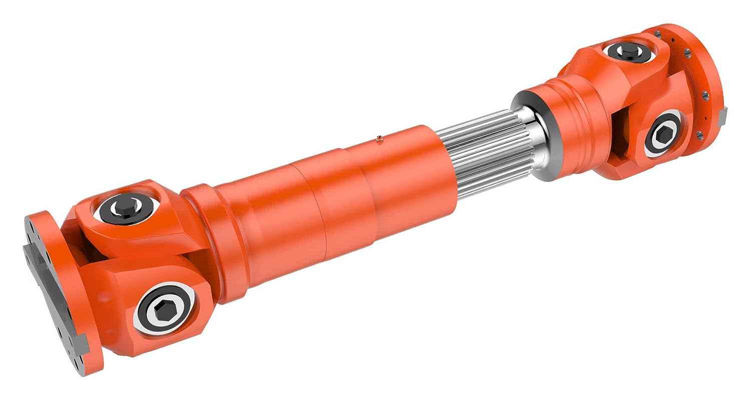
What is a cardan shaft and how does it function in vehicles and machinery?
A cardan shaft, also known as a propeller shaft or drive shaft, is a mechanical component used in vehicles and machinery to transmit torque and rotational power between two points that are not in line with each other. It consists of a tubular shaft with universal joints at each end, allowing for flexibility and accommodating misalignment between the driving and driven components. The cardan shaft plays a crucial role in transferring power from the engine or power source to the wheels or driven machinery. Here’s how it functions in vehicles and machinery:
1. Torque Transmission:
– In vehicles, the cardan shaft connects the transmission or gearbox to the differential, which then distributes torque to the wheels. When the engine generates rotational power, it is transmitted through the transmission to the cardan shaft. The universal joints at each end of the shaft allow for angular misalignment and compensate for variations in the suspension, axle movement, and road conditions. As the cardan shaft rotates, it transfers torque from the transmission to the differential, enabling power delivery to the wheels.
– In machinery, the cardan shaft serves a similar purpose of transmitting torque between the power source and driven components. For example, in agricultural equipment, the cardan shaft connects the tractor’s PTO (Power Take-Off) to various implements such as mowers, balers, or tillers. The rotational power from the tractor’s engine is transferred through the PTO driveline to the cardan shaft, which then transmits the torque to the driven machinery, enabling their operation.
2. Flexibility and Compensation:
– The cardan shaft’s design with universal joints provides flexibility and compensates for misalignment between the driving and driven components. The universal joints allow the shaft to bend and articulate while maintaining a continuous torque transmission. This flexibility is essential in vehicles and machinery where the driving and driven components may be at different angles or positions due to suspension movement, axle articulation, or uneven terrain. The cardan shaft absorbs these variations and ensures smooth power delivery without causing excessive stress or vibration.
3. Balancing and Vibration Control:
– Cardan shafts also contribute to balancing and vibration control in vehicles and machinery. The rotation of the shaft generates centrifugal forces, and any imbalance can result in vibration and reduced performance. To counterbalance this, cardan shafts are carefully designed and balanced to minimize vibration and provide smooth operation. Additionally, the universal joints help in absorbing minor vibrations and reducing their transmission to the vehicle or machinery.
4. Length Adjustment:
– Cardan shafts offer the advantage of adjustable length, allowing for variations in the distance between the driving and driven components. This adjustability is particularly useful in vehicles and machinery with adjustable wheelbases or variable attachment points. By adjusting the length of the cardan shaft, the driveline can be appropriately sized and positioned to accommodate different configurations, ensuring optimal power transmission efficiency.
5. Safety Features:
– Cardan shafts in vehicles and machinery often incorporate safety features to protect against mechanical failures. These may include shielding or guards to prevent contact with rotating components, such as the driveshaft or universal joints. In the event of a joint failure or excessive force, some cardan shafts may also incorporate shear pins or torque limiters to prevent damage to the driveline and protect other components from excessive loads.
In summary, a cardan shaft is a tubular component with universal joints at each end used to transmit torque and rotational power between non-aligned driving and driven components. It provides flexibility, compensates for misalignment, and enables torque transmission in vehicles and machinery. By efficiently transferring power, accommodating variations, and balancing vibrations, cardan shafts play a critical role in ensuring smooth and reliable operation in a wide range of applications.


editor by CX 2024-03-08