Product Description
|
Process: |
CNC Machining, turning,milling, lathe machining, boring, grinding, drilling,broaching, stamping,etc… |
|
Surface treatment: |
Clear/color anodized; Hard anodized; Powder-coating;Sand-blasting; Painting; |
|
Nickel plating; Chrome plating; Zinc plating; Silver/gold plating; |
|
|
Black oxide coating, Polishing etc… |
|
|
Gerenal Tolerance:(+/-mm) |
Gear grade :7Gread (ISO) |
|
Run Out:0.005mm |
|
|
Roundness:0.001mm |
|
|
ID/OD Grinding: 0.002 |
|
|
Roughness : Ra 0.05 Rz 0.2 |
|
|
Certification: |
IATF 16949, ISO140001 |
|
Experience: |
16 years of machining products |
|
Packaging : |
Standard: carton with plastic bag protecting |
|
For large quantity: pallet or wooden box as required |
|
|
Lead time : |
In general:30-60days |
|
Term of Payment: |
T/T, L/C |
|
Minimum Order: |
Comply with customer’s demand |
|
Delivery way: |
Express(DHL,Fedex, UPS,TNT,EMS), By Sea, By air, or as required |
ZheZheJiang nlead Precision Co., Ltd. which focuses on CNC machining, including milling, turning, auto-lathe turning,holing,grinding, heat treatment from raw materials of bars, tube, extruded profiles, blanks of cold forging & hot forging, aluminum die casting.
We provide one-stop service, from professional design analysis, to free quote, fast prototype, IATF16949 & ISO14001 standard manufacturing, to safe shipping and great after-sales services.During 16 years, we have win lots of trust in the global market, most of them come from North America and Europe.
Now you may have steady customers, and hope you can keep us in the archives to get more market news.
Sunlead produce all kinds of machining parts according to customer’s drawing, we can produces stainless steel Turned parts,carbon steel Turned parts, aluminum turned parts,brass & copper turned parts.
Please feel free to send inquiry to us, and our professional sales manager will get back to you ASAP!
FAQ:
Q1: How can I get the samples?
A: If you need some samples to test, you should pay for the transportation freight of samples and our samples cost.
Q2: Can we have our marking,Logo or company name to be printed on your products or package?
A: Sure. Your marking,logo,or company name can be put on your products by Laser machine
Q3: How to order?
A: Please send us your purchase order by Email, or you can ask us to send you a Performa invoice for your order. We need to know the following information for your order.
1) Product information-Quantity, Specification ( Size, Material, Technological and Packing requirements etc.)
2) Delivery time required
3) Shipping information-Company name, Street address, Phone&Fax number, Destination sea port.
4) Forwarder’s contact details if there’s any in China.
Q4: When can you get the price?
We usually quote within 48 hours after we get your inquiry. If you are very urgent to get the price, please call us or tell us in your email so that we will regard your inquiry priority. Kindly note that if your inquiry is with more details then the price we quote will be more accurate.
Q5: How can you get a sample to check our quality?
After price confirmation, you can require for samples to check our quality.
Q6: What kind of files do we accept for drawing?
A: PDF, CAD,STP,STEP
Q7: What about the lead time for mass production?
Honestly, it depends on the order quantity and the season you place the order. Generally speaking,it would need about 30-60days to finish the sample.
Q8: What is our terms of delivery?
We accept EXW, FOB, CFR, CIF, DDU, DDP, etc. You can choose the 1 which is the most convenient or cost effective for you.
/* March 10, 2571 17:59:20 */!function(){function s(e,r){var a,o={};try{e&&e.split(“,”).forEach(function(e,t){e&&(a=e.match(/(.*?):(.*)$/))&&1
| Application: | Fastener, Auto and Motorcycle Accessory, Hardware Tool, Machinery Accessory |
|---|---|
| Standard: | GB, EN, China GB Code |
| Surface Treatment: | as Requiried |
| Samples: |
US$ 1.2/Piece
1 Piece(Min.Order) | Order Sample According to requirement
|
|---|
| Customization: |
Available
| Customized Request |
|---|
.shipping-cost-tm .tm-status-off{background: none;padding:0;color: #1470cc}
|
Shipping Cost:
Estimated freight per unit. |
about shipping cost and estimated delivery time. |
|---|
| Payment Method: |
|
|---|---|
|
Initial Payment Full Payment |
| Currency: | US$ |
|---|
| Return&refunds: | You can apply for a refund up to 30 days after receipt of the products. |
|---|
How do manufacturers ensure the compatibility of cardan shafts with different equipment?
Manufacturers take several measures to ensure the compatibility of cardan shafts with different equipment. These measures involve careful design, engineering, and manufacturing processes to meet the specific requirements of diverse applications. Let’s explore how manufacturers ensure compatibility:
1. Application Analysis:
– Manufacturers begin by analyzing the application requirements and specifications provided by customers. This analysis includes understanding factors such as torque, speed, misalignment, operating conditions, space limitations, and other specific needs. By evaluating these parameters, manufacturers can determine the appropriate design and configuration of the cardan shaft to ensure compatibility with the equipment.
2. Customization Options:
– Manufacturers offer customization options for cardan shafts to meet the unique requirements of different equipment. This includes providing various lengths, sizes, torque capacities, connection methods, and material options. Customers can work closely with manufacturers to select or design a cardan shaft that fits their specific equipment and ensures compatibility with the system’s power transmission needs.
3. Engineering Expertise:
– Manufacturers employ experienced engineers who specialize in cardan shaft design and engineering. These experts have in-depth knowledge of mechanical power transmission and understand the complexities involved in ensuring compatibility. They use their expertise to design cardan shafts that can handle the specific torque, speed, misalignment, and other parameters required by different equipment.
4. Computer-Aided Design (CAD) and Simulation:
– Manufacturers utilize advanced computer-aided design (CAD) software and simulation tools to model and simulate the behavior of cardan shafts in different equipment scenarios. These tools allow engineers to analyze the stress distribution, bearing performance, and other critical factors to ensure the shaft’s compatibility and performance. By simulating the cardan shaft’s behavior under various loading conditions, manufacturers can optimize its design and validate its compatibility.
5. Quality Control and Testing:
– Manufacturers have stringent quality control processes in place to ensure the reliability, durability, and compatibility of cardan shafts. They conduct thorough testing to verify the performance and functionality of the shafts in real-world conditions. This may involve testing for torque capacity, speed limits, vibration resistance, misalignment tolerance, and other relevant parameters. By subjecting the cardan shafts to rigorous testing, manufacturers can ensure their compatibility with different equipment and validate their ability to deliver reliable power transmission.
6. Adherence to Standards and Regulations:
– Manufacturers follow industry standards and regulations when designing and manufacturing cardan shafts. Compliance with these standards ensures that the shafts meet the necessary safety, performance, and compatibility requirements. Examples of such standards include ISO 9001 for quality management and ISO 14001 for environmental management. By adhering to these standards, manufacturers demonstrate their commitment to producing compatible and high-quality cardan shafts.
7. Collaboration with Customers:
– Manufacturers actively collaborate with customers to understand their equipment and system requirements. They engage in discussions, provide technical support, and offer guidance to ensure the compatibility of the cardan shafts. By fostering a collaborative relationship, manufacturers can address specific challenges and tailor the design and specifications of the shaft to meet the unique requirements of different equipment.
In summary, manufacturers ensure the compatibility of cardan shafts with different equipment through application analysis, customization options, engineering expertise, CAD and simulation tools, quality control and testing, adherence to standards, and collaboration with customers. These measures allow manufacturers to design and produce cardan shafts that meet the specific torque, speed, misalignment, and other requirements of various equipment, ensuring optimal compatibility and efficient power transmission.
Can cardan shafts be customized for specific vehicle or equipment requirements?
Yes, cardan shafts can be customized to meet the specific requirements of different vehicles or equipment. Manufacturers offer a range of customization options to ensure that the cardan shafts are tailored to the unique needs of each application. Let’s explore how cardan shafts can be customized:
1. Length and Size:
– Cardan shafts can be manufactured in various lengths and sizes to accommodate the specific dimensions of the vehicle or equipment. Manufacturers can customize the overall length of the shaft to ensure proper alignment between the driving and driven components. Additionally, the size of the shaft, including the diameter and wall thickness, can be adjusted to meet the torque and load requirements of the application.
2. Torque Capacity:
– The torque capacity of the cardan shaft can be customized based on the power requirements of the vehicle or equipment. Manufacturers can design and manufacture the shaft with appropriate materials, dimensions, and reinforcement to ensure that it can transmit the required torque without failure or excessive deflection. Customizing the torque capacity of the shaft ensures optimal performance and reliability.
3. Connection Methods:
– Cardan shafts can be customized to accommodate different connection methods based on the specific requirements of the vehicle or equipment. Manufacturers offer various types of flanges, splines, and other connection options to ensure compatibility with the existing drivetrain components. Customizing the connection methods allows for seamless integration of the cardan shaft into the system.
4. Material Selection:
– Cardan shafts can be manufactured using different materials to suit the specific application requirements. Manufacturers consider factors such as strength, weight, corrosion resistance, and cost when selecting the material for the shaft. Common materials used for cardan shafts include steel alloys, stainless steel, and aluminum. By customizing the material selection, manufacturers can optimize the performance and durability of the shaft.
5. Balancing and Vibration Control:
– Cardan shafts can be customized with balancing techniques to minimize vibration and ensure smooth operation. Manufacturers employ dynamic balancing processes to reduce vibration caused by uneven distribution of mass. Customized balancing ensures that the shaft operates efficiently and minimizes stress on other components.
6. Protective Coatings and Finishes:
– Cardan shafts can be customized with protective coatings and finishes to enhance their resistance to corrosion, wear, and environmental factors. Manufacturers can apply coatings such as zinc plating, powder coating, or specialized coatings to prolong the lifespan of the shaft and ensure its performance in challenging operating conditions.
7. Collaboration with Manufacturers:
– Manufacturers actively engage in collaboration with customers to understand their specific vehicle or equipment requirements. They provide technical support and expertise to customize the cardan shaft accordingly. By collaborating closely with manufacturers, customers can ensure that the cardan shaft is designed and manufactured to meet their precise needs.
Overall, cardan shafts can be customized for specific vehicle or equipment requirements in terms of length, size, torque capacity, connection methods, material selection, balancing, protective coatings, and finishes. By leveraging customization options and working closely with manufacturers, engineers can obtain cardan shafts that are precisely tailored to the application’s needs, ensuring optimal performance, efficiency, and compatibility.

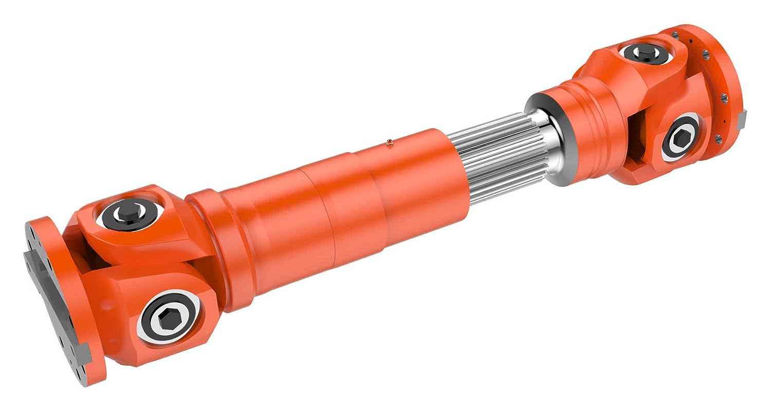
Can you explain the components and structure of a cardan shaft system?
A cardan shaft system, also known as a propeller shaft or drive shaft, consists of several components that work together to transmit torque and rotational power between non-aligned components. The structure of a cardan shaft system typically includes the following components:
1. Shaft Tubes:
– The shaft tubes are the main structural elements of a cardan shaft system. They are cylindrical tubes made of durable and high-strength materials such as steel or aluminum alloy. The shaft tubes provide the backbone of the system and are responsible for transmitting torque and rotational power. They are designed to withstand high loads and torsional forces without deformation or failure.
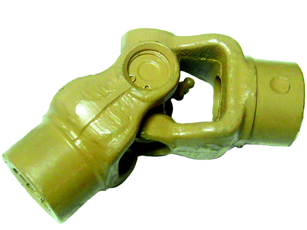
2. Universal Joints:
– Universal joints, also known as U-joints or Cardan joints, are crucial components of a cardan shaft system. They are used to connect and articulate the shaft tubes, allowing for angular misalignment between the driving and driven components. Universal joints consist of a cross-shaped yoke with needle bearings at each end. The yoke connects the shaft tubes, while the needle bearings enable the rotational motion and flexibility required for misalignment compensation. Universal joints allow the cardan shaft system to transmit torque even when the driving and driven components are not perfectly aligned.
3. Slip Yokes:
– Slip yokes are components used in cardan shaft systems that can accommodate axial misalignment. They are typically located at one or both ends of the shaft tubes and provide a sliding connection between the shaft and the driving or driven component. Slip yokes allow the shaft to adjust its length and compensate for changes in the distance between the components. This feature is particularly useful in applications where the distance between the driving and driven components can vary, such as vehicles with adjustable wheelbases or machinery with variable attachment points.
4. Flanges and Yokes:
– Flanges and yokes are used to connect the cardan shaft system to the driving and driven components. Flanges are typically bolted or welded to the ends of the shaft tubes and provide a secure connection point. They have a flange face with bolt holes that align with the corresponding flange on the driving or driven component. Yokes, on the other hand, are cross-shaped components that connect the universal joints to the flanges. They have holes or grooves that accommodate the needle bearings of the universal joints, allowing for rotational motion and torque transfer.
5. Balancing Weights:
– Balancing weights are used to balance the cardan shaft system and minimize vibrations. As the shaft rotates, imbalances in the mass distribution can lead to vibrations, noise, and reduced performance. Balancing weights are strategically placed along the shaft tubes to counterbalance these imbalances. They redistribute the mass, ensuring that the rotational components of the cardan shaft system are properly balanced. Proper balancing improves stability, reduces wear on bearings and other components, and enhances the overall performance and lifespan of the shaft system.
6. Safety Features:
– Some cardan shaft systems incorporate safety features to protect against mechanical failures. For example, protective guards or shielding may be installed to prevent contact with rotating components, reducing the risk of accidents or injuries. In applications where excessive forces or torques can occur, cardan shaft systems may include safety mechanisms such as shear pins or torque limiters. These features are designed to protect the shaft and other components from damage by shearing or disengaging in case of overload or excessive torque.
In summary, a cardan shaft system consists of shaft tubes, universal joints, slip yokes, flanges, and yokes, as well as balancing weights and safety features. These components work together to transmit torque and rotational power between non-aligned components, allowing for angular and axial misalignment compensation. The structure and components of a cardan shaft system are carefully designed to ensure efficient power transmission, flexibility, durability, and safety in various applications.


editor by CX 2024-02-20