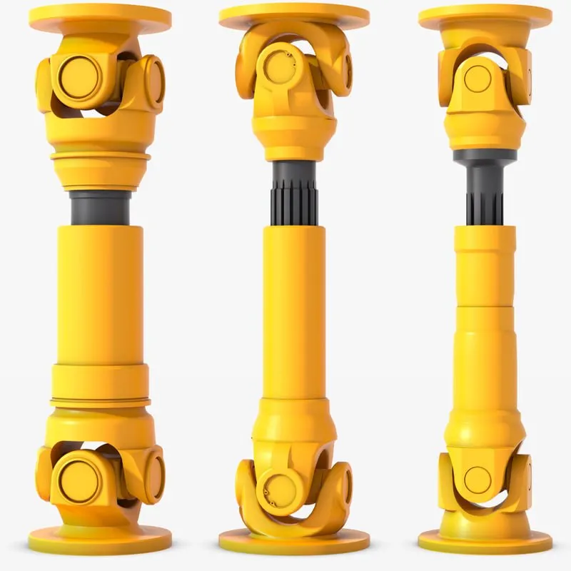
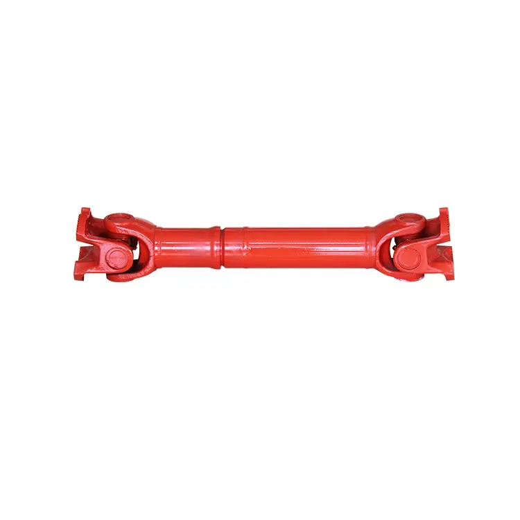
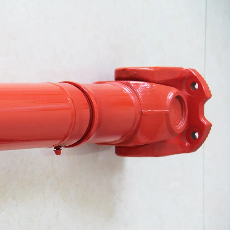
Product Description
| Product Name | Cardan Shaft |
| Product Model | SWC-I75A-335+40 |
| Main Material | 35CrMo or 45# Steel |
| Nominal Torque | 500 N.M |
| Normal Length | 335 mm |
| Length Compensation | 40 mm |
/* March 10, 2571 17:59:20 */!function(){function s(e,r){var a,o={};try{e&&e.split(“,”).forEach(function(e,t){e&&(a=e.match(/(.*?):(.*)$/))&&1
| Standard Or Nonstandard: | Nonstandard |
|---|---|
| Shaft Hole: | 19-32 |
| Torque: | >80N.M |
| Samples: |
US$ 10/Piece
1 Piece(Min.Order) | Order Sample |
|---|
| Customization: |
Available
| Customized Request |
|---|
.shipping-cost-tm .tm-status-off{background: none;padding:0;color: #1470cc}
| Shipping Cost:
Estimated freight per unit. |
about shipping cost and estimated delivery time. |
|---|
| Payment Method: |
|
|---|---|
|
Initial Payment Full Payment |
| Currency: | US$ |
|---|
| Return&refunds: | You can apply for a refund up to 30 days after receipt of the products. |
|---|
Can cardan shafts be adapted for use in both automotive and industrial settings?
Yes, cardan shafts can be adapted for use in both automotive and industrial settings. They are versatile components that offer efficient power transmission and can be customized to meet the specific requirements of various applications. Let’s explore how cardan shafts can be adapted for both automotive and industrial settings:
1. Automotive Applications:
– Cardan shafts have long been used in automotive applications, especially in vehicles with rear-wheel drive or all-wheel drive systems. They are commonly found in cars, trucks, SUVs, and commercial vehicles. In the automotive sector, cardan shafts are primarily used to transmit torque from the engine or transmission to the differential or axle, allowing power to be distributed to the wheels. They provide a reliable and efficient means of transferring power, even in vehicles that experience varying loads, vibration, and misalignment. Cardan shafts in automotive applications are typically designed to handle specific torque and speed requirements, taking into account factors such as vehicle weight, horsepower, and intended use.
2. Industrial Applications:
– Cardan shafts are also widely used in various industrial settings where torque needs to be transmitted between two rotating components. They are employed in a diverse range of industries, including manufacturing, mining, agriculture, construction, and more. In industrial applications, cardan shafts are utilized in machinery, equipment, and systems that require efficient power transmission over long distances or in situations where angular misalignment is present. Industrial cardan shafts can be customized to accommodate specific torque, speed, and misalignment requirements, considering factors such as the load, rotational speed, operating conditions, and space constraints. They are commonly used in applications such as conveyors, pumps, generators, mixers, crushers, and other industrial machinery.
3. Customization and Adaptability:
– Cardan shafts can be adapted for various automotive and industrial applications through customization. Manufacturers offer a range of cardan shaft options with different lengths, sizes, torque capacities, and speed ratings to suit specific requirements. Universal joints, slip yokes, telescopic sections, and other components can be selected or designed to meet the demands of different settings. Additionally, cardan shafts can be made from different materials, such as steel or aluminum alloy, depending on the application’s needs for strength, durability, or weight reduction. By collaborating with cardan shaft manufacturers and suppliers, automotive and industrial engineers can adapt these components to their specific settings, ensuring optimal performance and reliability.
4. Consideration of Application-Specific Factors:
– When adapting cardan shafts for automotive or industrial settings, it is crucial to consider application-specific factors. These factors may include torque requirements, speed limits, operating conditions (temperature, humidity, etc.), space limitations, and the need for maintenance and serviceability. By carefully evaluating these factors and collaborating with experts, engineers can select or design cardan shafts that meet the unique demands of the automotive or industrial application.
In summary, cardan shafts can be adapted and customized for use in both automotive and industrial settings. Their versatility, efficient power transmission capabilities, and ability to accommodate misalignment make them suitable for a wide range of applications. By considering the specific requirements and collaborating with cardan shaft manufacturers, engineers can ensure that these components provide reliable and efficient power transfer in automotive and industrial systems.

Are there any emerging trends in cardan shaft technology, such as lightweight materials?
Yes, there are several emerging trends in cardan shaft technology, including the use of lightweight materials and advancements in design and manufacturing techniques. These trends aim to improve the performance, efficiency, and durability of cardan shafts. Here are some of the notable developments:
1. Lightweight Materials:
– The automotive and manufacturing industries are increasingly exploring the use of lightweight materials in cardan shaft construction. Materials such as aluminum alloys and carbon fiber-reinforced composites offer significant weight reduction compared to traditional steel shafts. The use of lightweight materials helps reduce the overall weight of the vehicle or machinery, leading to improved fuel efficiency, increased payload capacity, and enhanced performance.
2. Advanced Composite Materials:
– Advanced composite materials, such as carbon fiber and fiberglass composites, are being utilized in cardan shafts to achieve a balance between strength, stiffness, and weight reduction. These materials offer high tensile strength, excellent fatigue resistance, and corrosion resistance. By incorporating advanced composites, cardan shafts can achieve reduced weight while maintaining the necessary structural integrity and durability.
3. Enhanced Design and Optimization:
– Advanced computer-aided design (CAD) and simulation techniques are being employed to optimize the design of cardan shafts. Finite element analysis (FEA) and computational fluid dynamics (CFD) simulations allow for better understanding of the structural behavior, stress distribution, and performance characteristics of the shafts. This enables engineers to design more efficient and lightweight cardan shafts that meet specific performance requirements.
4. Additive Manufacturing (3D Printing):
– Additive manufacturing, commonly known as 3D printing, is gaining traction in the production of cardan shafts. This technology allows for complex geometries and customized designs to be manufactured with reduced material waste. Additive manufacturing also enables the integration of lightweight lattice structures, which further enhances weight reduction without compromising strength. The flexibility of 3D printing enables the production of cardan shafts that are tailored to specific applications, optimizing performance and reducing costs.
5. Surface Coatings and Treatments:
– Surface coatings and treatments are being employed to improve the durability, corrosion resistance, and friction characteristics of cardan shafts. Advanced coatings such as ceramic coatings, diamond-like carbon (DLC) coatings, and nanocomposite coatings enhance the surface hardness, reduce friction, and protect against wear and corrosion. These treatments extend the lifespan of cardan shafts and contribute to the overall efficiency and reliability of the power transmission system.
6. Integrated Sensor Technology:
– The integration of sensor technology in cardan shafts is an emerging trend. Sensors can be embedded in the shafts to monitor parameters such as torque, vibration, and temperature. Real-time data from these sensors can be used for condition monitoring, predictive maintenance, and performance optimization. Integrated sensor technology allows for proactive maintenance, reducing downtime and improving the overall operational efficiency of vehicles and machinery.
These emerging trends in cardan shaft technology, including the use of lightweight materials, advanced composites, enhanced design and optimization, additive manufacturing, surface coatings, and integrated sensor technology, are driving advancements in the performance, efficiency, and reliability of cardan shafts. These developments aim to meet the evolving demands of various industries and contribute to more sustainable and high-performing power transmission systems.
What is a cardan shaft and how does it function in vehicles and machinery?
A cardan shaft, also known as a propeller shaft or drive shaft, is a mechanical component used in vehicles and machinery to transmit torque and rotational power between two points that are not in line with each other. It consists of a tubular shaft with universal joints at each end, allowing for flexibility and accommodating misalignment between the driving and driven components. The cardan shaft plays a crucial role in transferring power from the engine or power source to the wheels or driven machinery. Here’s how it functions in vehicles and machinery:
1. Torque Transmission:
– In vehicles, the cardan shaft connects the transmission or gearbox to the differential, which then distributes torque to the wheels. When the engine generates rotational power, it is transmitted through the transmission to the cardan shaft. The universal joints at each end of the shaft allow for angular misalignment and compensate for variations in the suspension, axle movement, and road conditions. As the cardan shaft rotates, it transfers torque from the transmission to the differential, enabling power delivery to the wheels.
– In machinery, the cardan shaft serves a similar purpose of transmitting torque between the power source and driven components. For example, in agricultural equipment, the cardan shaft connects the tractor’s PTO (Power Take-Off) to various implements such as mowers, balers, or tillers. The rotational power from the tractor’s engine is transferred through the PTO driveline to the cardan shaft, which then transmits the torque to the driven machinery, enabling their operation.
2. Flexibility and Compensation:
– The cardan shaft’s design with universal joints provides flexibility and compensates for misalignment between the driving and driven components. The universal joints allow the shaft to bend and articulate while maintaining a continuous torque transmission. This flexibility is essential in vehicles and machinery where the driving and driven components may be at different angles or positions due to suspension movement, axle articulation, or uneven terrain. The cardan shaft absorbs these variations and ensures smooth power delivery without causing excessive stress or vibration.
3. Balancing and Vibration Control:
– Cardan shafts also contribute to balancing and vibration control in vehicles and machinery. The rotation of the shaft generates centrifugal forces, and any imbalance can result in vibration and reduced performance. To counterbalance this, cardan shafts are carefully designed and balanced to minimize vibration and provide smooth operation. Additionally, the universal joints help in absorbing minor vibrations and reducing their transmission to the vehicle or machinery.
4. Length Adjustment:
– Cardan shafts offer the advantage of adjustable length, allowing for variations in the distance between the driving and driven components. This adjustability is particularly useful in vehicles and machinery with adjustable wheelbases or variable attachment points. By adjusting the length of the cardan shaft, the driveline can be appropriately sized and positioned to accommodate different configurations, ensuring optimal power transmission efficiency.
5. Safety Features:
– Cardan shafts in vehicles and machinery often incorporate safety features to protect against mechanical failures. These may include shielding or guards to prevent contact with rotating components, such as the driveshaft or universal joints. In the event of a joint failure or excessive force, some cardan shafts may also incorporate shear pins or torque limiters to prevent damage to the driveline and protect other components from excessive loads.
In summary, a cardan shaft is a tubular component with universal joints at each end used to transmit torque and rotational power between non-aligned driving and driven components. It provides flexibility, compensates for misalignment, and enables torque transmission in vehicles and machinery. By efficiently transferring power, accommodating variations, and balancing vibrations, cardan shafts play a critical role in ensuring smooth and reliable operation in a wide range of applications.


editor by CX 2024-02-21
China Standard Flexible Nonstandard Woodon China Gear Coupling Cardan Shaft Balancing Machine
Product Description
| Product Name | Cardan Shaft |
| Product Model | SWC-I75A-335+40 |
| Main Material | 35CrMo or 45# Steel |
| Nominal Torque | 500 N.M |
| Normal Length | 335 mm |
| Length Compensation | 40 mm |
| Standard Or Nonstandard: | Nonstandard |
|---|---|
| Shaft Hole: | 19-32 |
| Torque: | >80N.M |
| Samples: |
US$ 10/Piece
1 Piece(Min.Order) | Order Sample |
|---|
| Customization: |
Available
| Customized Request |
|---|
.shipping-cost-tm .tm-status-off{background: none;padding:0;color: #1470cc}
| Shipping Cost:
Estimated freight per unit. |
about shipping cost and estimated delivery time. |
|---|
| Payment Method: |
|
|---|---|
|
Initial Payment Full Payment |
| Currency: | US$ |
|---|
| Return&refunds: | You can apply for a refund up to 30 days after receipt of the products. |
|---|
How do cardan shafts ensure efficient power transfer while maintaining balance?
Cardan shafts are designed to ensure efficient power transfer while maintaining balance between the driving and driven components. They employ various mechanisms and features that contribute to both aspects. Let’s explore how cardan shafts achieve efficient power transfer and balance:
1. Universal Joints:
– Cardan shafts utilize universal joints, also known as U-joints, to transmit torque from the driving component to the driven component. Universal joints consist of a cross-shaped yoke with needle bearings at each end. These needle bearings allow the joints to pivot and accommodate angular misalignment between the driving and driven components. By allowing for flexibility in movement, universal joints ensure efficient power transfer even when the components are not perfectly aligned, minimizing energy losses and maintaining balance.
2. Misalignment Compensation:
– Cardan shafts are designed to compensate for misalignment between the driving and driven components. The universal joints, along with slip yokes and telescopic sections, allow the shaft to adjust its length and accommodate variations in alignment. This misalignment compensation capability ensures that the cardan shaft can transmit power smoothly and efficiently, reducing stress on the components and maintaining balance during operation.
3. Balanced Design:
– Cardan shafts are engineered with a balanced design to minimize vibration and maintain smooth operation. The shaft tubes are typically symmetrically constructed, and the universal joints are positioned to distribute the mass evenly. This balanced design helps to reduce vibration and minimize the occurrence of unbalanced forces that can negatively impact power transfer and overall system performance. By maintaining balance, cardan shafts contribute to efficient power transmission and improve the lifespan of the components involved.
4. High-Quality Materials and Manufacturing:
– The materials used in the construction of cardan shafts, such as steel or aluminum alloy, are carefully selected for their strength, durability, and ability to maintain balance. High-quality materials ensure that the shafts can withstand the torque and operational stresses without deformation or failure, promoting efficient power transfer. Additionally, precise manufacturing processes and quality control measures are employed to ensure that the cardan shafts are accurately balanced during production, further enhancing their efficiency and balance.
5. Regular Maintenance and Inspection:
– To ensure continued efficient power transfer and balance, regular maintenance and inspection of cardan shafts are essential. This includes periodic lubrication of the universal joints, checking for wear or damage, and addressing any misalignment issues. Regular maintenance helps to preserve the balance of the shaft and ensures optimal performance and longevity.
Overall, cardan shafts ensure efficient power transfer while maintaining balance through the use of universal joints for torque transmission, misalignment compensation mechanisms, balanced design, high-quality materials, and regular maintenance. By incorporating these features, cardan shafts contribute to the smooth operation, reliability, and longevity of various applications in automotive, industrial, and other sectors that rely on efficient power transmission.
Can you provide real-world examples of vehicles and machinery that use cardan shafts?
Cardan shafts are widely used in various vehicles and machinery across different industries. They are employed in applications where torque transmission, power distribution, and flexibility are crucial. Here are some real-world examples of vehicles and machinery that utilize cardan shafts:
1. Automotive Vehicles:
– Cars, trucks, and SUVs: Cardan shafts are commonly found in rear-wheel drive (RWD) and four-wheel drive (4WD) vehicles. They connect the transmission or transfer case to the rear differential or front differential, respectively, enabling torque transmission to the wheels. Examples include sedans, pickup trucks, and SUVs like Jeep Wrangler, Ford F-150, and Toyota Land Cruiser.
– Buses and commercial vehicles: Cardan shafts are used in buses and commercial vehicles that have rear-wheel drive or all-wheel drive configurations. They transmit torque from the engine or transmission to the rear axle or multiple axles. Examples include city buses, coaches, and delivery trucks.
2. Off-Road and Utility Vehicles:
– Off-road vehicles: Many off-road vehicles, such as off-road trucks, SUVs, and all-terrain vehicles (ATVs) utilize cardan shafts. These shafts provide the necessary torque transfer and power distribution to all wheels for improved traction and off-road capabilities. Examples include the Land Rover Defender, Jeep Wrangler Rubicon, and Yamaha Grizzly ATV.
– Agricultural machinery: Farm equipment like tractors and combine harvesters often employ cardan shafts to transmit power from the engine to various attachments such as mowers, balers, and harvesters. The shafts enable efficient power distribution and flexibility for different agricultural tasks.
– Construction and mining machinery: Equipment used in construction and mining applications, such as excavators, loaders, and bulldozers, utilize cardan shafts to transfer power from the engine or transmission to the different components of the machinery. These shafts enable power distribution and torque transmission to various attachments, allowing for efficient operation in demanding environments.
3. Industrial Machinery:
– Manufacturing machinery: Cardan shafts are used in industrial equipment such as conveyors, mixers, and rotary equipment. They provide torque transmission and power distribution within the machinery, enabling efficient operation and movement of materials.
– Paper and pulp industry: Cardan shafts are employed in paper and pulp processing machinery, including paper machines and pulp digesters. These shafts facilitate power transmission and torque distribution to various parts of the machinery, contributing to smooth operation and high productivity.
– Steel and metal processing machinery: Equipment used in steel mills and metal processing facilities, such as rolling mills, extruders, and coil winding machines, often utilize cardan shafts. These shafts enable power transmission and torque distribution to the different components involved in metal forming, shaping, and processing.
These examples represent just a few of the many applications where cardan shafts are employed. Their versatility, durability, and ability to handle torque transmission and power distribution make them essential components in a wide range of vehicles and machinery across industries.

Can you explain the components and structure of a cardan shaft system?
A cardan shaft system, also known as a propeller shaft or drive shaft, consists of several components that work together to transmit torque and rotational power between non-aligned components. The structure of a cardan shaft system typically includes the following components:
1. Shaft Tubes:
– The shaft tubes are the main structural elements of a cardan shaft system. They are cylindrical tubes made of durable and high-strength materials such as steel or aluminum alloy. The shaft tubes provide the backbone of the system and are responsible for transmitting torque and rotational power. They are designed to withstand high loads and torsional forces without deformation or failure.
2. Universal Joints:
– Universal joints, also known as U-joints or Cardan joints, are crucial components of a cardan shaft system. They are used to connect and articulate the shaft tubes, allowing for angular misalignment between the driving and driven components. Universal joints consist of a cross-shaped yoke with needle bearings at each end. The yoke connects the shaft tubes, while the needle bearings enable the rotational motion and flexibility required for misalignment compensation. Universal joints allow the cardan shaft system to transmit torque even when the driving and driven components are not perfectly aligned.
3. Slip Yokes:
– Slip yokes are components used in cardan shaft systems that can accommodate axial misalignment. They are typically located at one or both ends of the shaft tubes and provide a sliding connection between the shaft and the driving or driven component. Slip yokes allow the shaft to adjust its length and compensate for changes in the distance between the components. This feature is particularly useful in applications where the distance between the driving and driven components can vary, such as vehicles with adjustable wheelbases or machinery with variable attachment points.
4. Flanges and Yokes:
– Flanges and yokes are used to connect the cardan shaft system to the driving and driven components. Flanges are typically bolted or welded to the ends of the shaft tubes and provide a secure connection point. They have a flange face with bolt holes that align with the corresponding flange on the driving or driven component. Yokes, on the other hand, are cross-shaped components that connect the universal joints to the flanges. They have holes or grooves that accommodate the needle bearings of the universal joints, allowing for rotational motion and torque transfer.
5. Balancing Weights:
– Balancing weights are used to balance the cardan shaft system and minimize vibrations. As the shaft rotates, imbalances in the mass distribution can lead to vibrations, noise, and reduced performance. Balancing weights are strategically placed along the shaft tubes to counterbalance these imbalances. They redistribute the mass, ensuring that the rotational components of the cardan shaft system are properly balanced. Proper balancing improves stability, reduces wear on bearings and other components, and enhances the overall performance and lifespan of the shaft system.
6. Safety Features:
– Some cardan shaft systems incorporate safety features to protect against mechanical failures. For example, protective guards or shielding may be installed to prevent contact with rotating components, reducing the risk of accidents or injuries. In applications where excessive forces or torques can occur, cardan shaft systems may include safety mechanisms such as shear pins or torque limiters. These features are designed to protect the shaft and other components from damage by shearing or disengaging in case of overload or excessive torque.
In summary, a cardan shaft system consists of shaft tubes, universal joints, slip yokes, flanges, and yokes, as well as balancing weights and safety features. These components work together to transmit torque and rotational power between non-aligned components, allowing for angular and axial misalignment compensation. The structure and components of a cardan shaft system are carefully designed to ensure efficient power transmission, flexibility, durability, and safety in various applications.
editor by CX 2023-11-10
China supplier Forging Gear Pinion Shaft for Transmission System of Grinding Machine drive shaft axle
Product Description
About us:
CIC is a more than 30-year manufacturer and reputed supplier of forged shaft used in various machinery equipment in the fields of mining, metallurgical, chemical industry, construction, and so on. CIC possesses professional design team, advanced equipment and detecting method, strict quality control system to meet all your customized requirements of forged shaft. High quality, excellent performances and competitive price will make you rely on us and choose us.
CIC has manufactured many kinds of forged shafts, including forged roller, support roller forged shafts, thrust roller forged shafts, forged pinion shaft with gears both mounted to the shaft and as a part of the shaft, and other more kinds of forged shafts.
Bring us your challenges, and we will deliver solutions.
Attributes:
one. Material: stainless steel, carbon steel, alloy steel and as your requests
2. Standard: ANSI, API, ASTM, BSI, DIN, GB, ISO, JIS and more standards.
3. Mechanical Properties: customized requirements are accepted.
4. Hardness: customized requirements are accepted.
5. Surface treatment: rust preventive oil and according to your requirements.
six. Application: mainly used in various machinery equipment in the fields of mining, metallurgical, chemical industry, construction, and so on
7. QA and DOC: chemical composition report, mechanical properties report, UT report, PT report, heat treatment report, dimensions check report, hardness report and more
We can offer third party inspection.
eight. Process: raw material purchasing – forging – rough machining(rough hobbing) – heat treatment – semi machining (semi final hobbing) – hardening of tooth surfaces – finish machining(gear grinding) – painting and packing
Various process conditions are available.
9. Certificates: ISO 9001:2008
ten. Products ability: Max module:forty five
eleven. Heat treatment: quenching and tempering, normalizing and tempering.
12. Tooth surface treatment: carburizing and quenching, surface quenching
13. QC: fabrication schedule, fabrication process chart, inspection and test plan
14. Packing: coated with rust preventive oil, seaworthy packing
Benefits:
one. More than 30 years experience
2. ISO9001:2008 Standard certified
three. Custom-made design
4. All seamless forged
5. Strict quality control
6. Prompt delivery
Parameters:
| Identify |
Pinion Shaft |
|
Materials |
Forging carbon metal, forging alloy steel |
|
Diameter |
Max. 2m |
|
Duration |
Max. 20m |
|
Module |
Max. forty five |
Primary Manufacturing Devices:
two×8m Numerical Controlled Horizontal Lathe
6×20m heavy Horizontal Lathe
Gear Cutting & Hobbing Machine
| Material: | Alloy Steel |
|---|---|
| Load: | Drive Shaft |
| Stiffness & Flexibility: | Stiffness / Rigid Axle |
| Journal Diameter Dimensional Accuracy: | According to The Customer′s Requirement |
| Axis Shape: | Straight Shaft |
| Shaft Shape: | Stepped Shaft |
| Customization: |
Available
| Customized Request |
|---|
Why Checking the Drive Shaft is Important
If you hear clicking noises while driving, your driveshaft may need repair. An experienced mechanic can tell if the noise is coming from one side or both sides. This problem is usually related to the torque converter. Read on to learn why it’s so important to have your driveshaft inspected by an auto mechanic. Here are some symptoms to look for. Clicking noises can be caused by many different things. You should first check if the noise is coming from the front or the rear of the vehicle.
hollow drive shaft
Hollow driveshafts have many benefits. They are light and reduce the overall weight of the vehicle. The largest manufacturer of these components in the world is CZPT. They also offer lightweight solutions for various applications, such as high-performance axles. CZPT driveshafts are manufactured using state-of-the-art technology. They offer excellent quality at competitive prices.
The inner diameter of the hollow shaft reduces the magnitude of the internal forces, thereby reducing the amount of torque transmitted. Unlike solid shafts, hollow shafts are getting stronger. The material inside the hollow shaft is slightly lighter, which further reduces its weight and overall torque. However, this also increases its drag at high speeds. This means that in many applications hollow driveshafts are not as efficient as solid driveshafts.
A conventional hollow drive shaft consists of a first rod 14 and a second rod 14 on both sides. The first rod is connected with the second rod, and the second rod extends in the rotation direction. The two rods are then friction welded to the central area of the hollow shaft. The frictional heat generated during the relative rotation helps to connect the two parts. Hollow drive shafts can be used in internal combustion engines and environmentally-friendly vehicles.
The main advantage of a hollow driveshaft is weight reduction. The splines of the hollow drive shaft can be designed to be smaller than the outside diameter of the hollow shaft, which can significantly reduce weight. Hollow shafts are also less likely to jam compared to solid shafts. Hollow driveshafts are expected to eventually occupy the world market for automotive driveshafts. Its advantages include fuel efficiency and greater flexibility compared to solid prop shafts.
Cardan shaft
Cardan shafts are a popular choice in industrial machinery. They are used to transmit power from one machine to another and are available in a variety of sizes and shapes. They are available in a variety of materials, including steel, copper, and aluminum. If you plan to install one of these shafts, it is important to know the different types of Cardan shafts available. To find the best option, browse the catalog.
Telescopic or “Cardan” prop shafts, also known as U-joints, are ideal for efficient torque transfer between the drive and output system. They are efficient, lightweight, and energy-efficient. They employ advanced methods, including finite element modeling (FEM), to ensure maximum performance, weight, and efficiency. Additionally, the Cardan shaft has an adjustable length for easy repositioning.
Another popular choice for driveshafts is the Cardan shaft, also known as a driveshaft. The purpose of the driveshaft is to transfer torque from the engine to the wheels. They are typically used in high-performance car engines. Some types are made of brass, iron, or steel and have unique surface designs. Cardan shafts are available in inclined and parallel configurations.
Single Cardan shafts are a common replacement for standard Cardan shafts, but if you are looking for dual Cardan shafts for your vehicle, you will want to choose the 1310 series. This type is great for lifted jeeps and requires a CV-compatible transfer case. Some even require axle spacers. The dual Cardan shafts are also designed for lifts, which means it’s a good choice for raising and lowering jeeps.
universal joint
Cardan joints are a good choice for drive shafts when operating at a constant speed. Their design allows a constant angular velocity ratio between the input and output shafts. Depending on the application, the recommended speed limit may vary depending on the operating angle, transmission power, and application. These recommendations must be based on pressure. The maximum permissible speed of the drive shaft is determined by determining the angular acceleration.
Because gimbal joints don’t require grease, they can last a long time but eventually fail. If they are poorly lubricated or dry, they can cause metal-to-metal contact. The same is true for U-joints that do not have oil filling capability. While they have a long lifespan, it can be difficult to spot warning signs that could indicate impending joint failure. To avoid this, check the drive shaft regularly.
U-joints should not exceed seventy percent of their lateral critical velocity. However, if this speed is exceeded, the part will experience unacceptable vibration, reducing its useful life. To determine the best U-joint for your application, please contact your universal joint supplier. Typically, lower speeds do not require balancing. In these cases, you should consider using a larger pitch diameter to reduce axial force.
To minimize the angular velocity and torque of the output shaft, the two joints must be in phase. Therefore, the output shaft angular displacement does not completely follow the input shaft. Instead, it will lead or lag. Figure 3 illustrates the angular velocity variation and peak displacement lead of the gimbal. The ratios are shown below. The correct torque for this application is 1360 in-Ibs.
Refurbished drive shaft
Refurbished driveshafts are a good choice for a number of reasons. They are cheaper than brand new alternatives and generally just as reliable. Driveshafts are essential to the function of any car, truck, or bus. These parts are made of hollow metal tubes. While this helps reduce weight and expense, it is vulnerable to external influences. If this happens, it may crack or bend. If the shaft suffers this type of damage, it can cause serious damage to the transmission.
A car’s driveshaft is a critical component that transmits torque from the engine to the wheels. A1 Drive Shaft is a global supplier of automotive driveshafts and related components. Their factory has the capability to refurbish and repair almost any make or model of driveshafts. Refurbished driveshafts are available for every make and model of vehicle. They can be found on the market for a variety of vehicles, including passenger cars, trucks, vans, and SUVs.
Unusual noises indicate that your driveshaft needs to be replaced. Worn U-joints and bushings can cause excessive vibration. These components cause wear on other parts of the drivetrain. If you notice any of these symptoms, please take your vehicle to the AAMCO Bay Area Center for a thorough inspection. If you suspect damage to the driveshaft, don’t wait another minute – it can be very dangerous.
The cost of replacing the drive shaft
The cost of replacing a driveshaft varies, but on average, this repair costs between $200 and $1,500. While this price may vary by vehicle, the cost of parts and labor is generally equal. If you do the repair yourself, you should know how much the parts and labor will cost before you start work. Some parts can be more expensive than others, so it’s a good idea to compare the cost of several locations before deciding where to go.
If you notice any of these symptoms, you should seek a repair shop immediately. If you are still not sure if the driveshaft is damaged, do not drive the car any distance until it is repaired. Symptoms to look for include lack of power, difficulty moving the car, squeaking, clanking, or vibrating when the vehicle is moving.
Parts used in drive shafts include center support bearings, slip joints, and U-joints. The price of the driveshaft varies by vehicle and may vary by model of the same year. Also, different types of driveshafts require different repair methods and are much more expensive. Overall, though, a driveshaft replacement costs between $300 and $1,300. The process may take about an hour, depending on the vehicle model.
Several factors can lead to the need to replace the drive shaft, including bearing corrosion, damaged seals, or other components. In some cases, the U-joint indicates that the drive shaft needs to be replaced. Even if the bearings and u-joints are in good condition, they will eventually break and require the replacement of the drive shaft. However, these parts are not cheap, and if a damaged driveshaft is a symptom of a bigger problem, you should take the time to replace the shaft.
editor by CX 2023-04-13
in Amsterdam Netherlands sales price shop near me near me shop factory supplier Caigang Composite Plate Machine Gear Metering Pump Wholesaler manufacturer best Cost Custom Cheap wholesaler

we have received the have faith in of customers around the world. We are aiming to satisfy the requires of the consumers close to the world.. Good quality and credit rating are the bases that make a company alive. Caigang composite plate EPTT EPT metering pump EPTTsaler
A.[Item Description]
The design uEPTTzes higher stXiHu (West EPT) Dis.Hu (West EPT) Dis.rd exterior spur EPTs enclosed in a shut tolerance housing assembly. This offers you the exact quantity of fluid dispensed for every shaft revolution. The housing is made from precision ground and lapped three-plate assembly. This assembly is aligned with dowels to allow close management of operating clearances. This construction technique in combination with a number of proprietary inner features is what guarantees specific, pulseless, and trustworthy movement unEPTTvarying process conditions. When HangEPT Instrument pumps are coupled with a pre-packaged, built-in, shut-loop pace handle and a compact motor EPTr assembly (AC or DC), HangEPT Instrument is in a position to provide the most specific and fleXiHu (West EPT) Dis.ble metering EPT pump system on the marketplace.
B.[Parameters]
| Product |
Displacement (CC/R) |
Complete Top | Base Peak | Min Inlet Stress | Max Outpet Pressure | Accuracy | Temperature |
| GWMP-.fifteen | .fifteen | 83 | 28.one | lt0.2Mpa | lt30Mpa | /-3% | 200 ordmC |
|
GWMP-.3 |
.three | eighty five | thirty.2 | lt0.2Mpa | lt30Mpa | /-3% | 200 ordmC |
| GWMP-.6 | .6 | eighty five | 32 | lt0.2Mpa | lt30Mpa | /-3% | two hundred ordmC |
| GWMP-1.2 | one.two | ninety | 34 | lt0.2Mpa | lt30Mpa | /-3% | 200 ordmC |
| GWMP-two.four | 2.four | one hundred | forty two | lt0.2Mpa | lt30Mpa | /-3% | 200 ordmC |
| GWMP-three.six | 3.6 | a hundred and five | fifty | lt0.2Mpa | lt30Mpa | /-three% | 200 ordmC |
| GWMP-six | 6 | 130 | 41 | lt0.2Mpa | lt30Mpa | /-3% | two hundred ordmC |
| GWMP-nine | nine | a hundred thirty five | forty six | lt0.2Mpa | lt30Mpa | /-3% | two hundred ordmC |
| GWMP-twelve | 12 | 140 | 51 | lt0.2Mpa | lt30Mpa | /-three% | 200 ordmC |
| GWMP-fifteen | fifteen | a hundred forty five | fifty six | lt0.2Mpa | lt30Mpa | /-3% | 200 ordmC |
| GWMP-twenty | 20 | one hundred fifty | 64 | lt0.2Mpa | lt30Mpa | /-3% | two hundred ordmC |
| GWMP-thirty | 30 | one hundred sixty five | eighty | lt0.2Mpa | lt30Mpa | /-three% | 200 ordmC |
| GWMP-forty | forty | ninety | 215 | lt0.2Mpa | lt30Mpa | /-3% | 200 ordmC |
| GWMP-50 | fifty | 97 | 215 | lt0.2Mpa | lt30Mpa | /-3% | two hundred ordmC |
| GWMP-60 | 60 | 104.five | 230 | lt0.2Mpa | lt30Mpa | /-3% | 200 ordmC |
| GWMP-75 | 75 | 112 | 230 | lt0.2Mpa | lt30Mpa | /-three% | two hundred ordmC |
| GWMP-eighty | eighty | EPTT | EPTT | lt0.2Mpa | lt30Mpa | /-three% | two hundred ordmC |
| GWMP-a hundred twenty five | 125 | EPTT |
EPTT |
lt0.2Mpa | lt30Mpa | /-3% | 200 ordmC |
Notice:Course of rotation: clockwise from the aXiHu (West EPT) Dis.s of rotation
| Model | 6CC | 9CC | 12CC | 15CC | 20CC | 25CC | 30CC |
| A | a hundred thirty | a hundred thirty five | one hundred forty | one hundred forty five | one hundred fifty | 158 | a hundred sixty five |
| B | forty one | 46 | fifty one | 56 | sixty four | seventy two | eighty |
| Min Inlet Strain | lt0.2Mpa |
| Functioning Pace | 5~200 R/min |
| Medium | EPT |
| Temperature | 200 ordmC |
| Max Outlet Stress | lt30Mpa |
| Circulation Capability | 6-thirty( /-30)CC/R |
| EPT | Merged seal |
| Product | .15CC | .3CC | .6CC | 1.2CC | 2.4CC | three.2CC | 3.6CC |
| A | eighty three | 85 | 85 | 90 | one hundred | 103 | one zero five |
| B | 28.one | 30.2 | 32 | 34 | 42 | 47.6 | fifty |
| Min Inlet Stress | lt0.2Mpa |
| Working Speed | five~200 R/min |
| Medium | EPT |
| Temperature | 200 ordmC |
| Max Outlet Strain | lt30Mpa |
| Flow Capability | .15-three.6( /-3%)cc/r |
| EPT | Combined |
C.[Set up]
D.[EPTT Details]
- Our EPTT is Leading ten Manufacture on Alibaba
- We have about thirty years of experience in Manufacture
- Our products have been exported to a lot more 100 coutries and location
- ISO,SGS,CE and more ceterficates for you reference
- Patent EPT and a lot more than 3 many years working life


in Puebla Mexico sales price shop near me near me shop factory supplier POM Machine Transmission Precision Injection Plastic Duplicate Spiral Helical Gear manufacturer best Cost Custom Cheap wholesaler

In this way, our products have continued to obtain industry acceptance and customers gratification above the past handful of years. EPG will usually adhere to it organization spirit of being sensible, revolutionary, productive and superb to make the top intercontinental transmission push. PersonnelOur revenue folks are properly qualified to accommodate your requests and speak English for your convenience.
POM EPTT EPTT precision EPT plastic replicate spiral helical EPT
| Item | EPTT EPTTd EPT plastic EPTs |
| Craft Approach | Plastic Injection or CNC machining |
| Plastic Granules |
UL, Food and drug administration, RoHS and so on. |
| EPTT EPTT | ISO9001 and ISO14001 |
| Molds EPT | S316,H13,718,738,P20,H13,420SS |
| Mould EPT | 300,000 photographs or 1,000,000 photographs or far more |
| Mildew Cavity | Solitary-cavity or two cavities or Multi-cavity |
| EPT | Nylon, PA66, NYLON with 30% EPT fibre, Stomach muscles, PP,Laptop,PE,POM,PVC,PU,TPR,TPE,TPU,PA,PET,EPTTPE,PMMA and so forth. |
| Molds cavity Hardness | sixty to 90 H.R.C |
| Size/EPTT | EPTs and parts proportions are according to drawings from client, and shades are EPT |
| Floor remedy | PoEPTTd or matte surface area, painting, texture, EPT aluminizing and can be stamped with symbol and many others. |
| Measurement Tolerance | plusmn0.05mm or a lot more precise |
| Operate Flow chart | Step1: Make tooling first of all and usual need two~~3 weeks. Step2: Produce and affirm samples. Step3: A single 7 days for mass manufacturing usual. |
| Samples confirmation and approval | Free of charge samples shipped for affirmation and shipping and delivery EPT paid by consumers |
| Deal | Internal distinct plastic bag/exterior carton/picket pallets/ or any other EPTT bundle as per customer’s needs. |
| Shipping Time | Total requires 2~~4weeks normal |
| Payment Phrases | PAYPAL, T/T, Western EPT |
| EPT | Typical FEDEX, UPS, DHL, TNT, EMS or base on customer’s need. |
Creation:
one. The personnel are trained to examine the EPTs and discover any defect in manufacturing in time.
two. QC will examine 1pcs each 100pcs in CNC machining, and EPTs will satisfy all dimension tolerances.
3. EPTs will be inspected at each and every action, and EPTs will be inspected before shipment, and all inspection documents will be retained in our manufacturing facility for a few several years.
four. Our product sales will deliver you photos at each EPTs creation steps, and you will know the thorough creation status, and you can discover any possibility of blunder, for our sales, QC and workers are trying to keep shut observe on all creation.
five. You will feel us doing work very cautiously to guarantee the good quality and effortless to perform with,
six. we cherish every inquiry, every single chance to make EPTs and parts and cherish each and every client.
High quality Management Method:
1) Inspecting the uncooked material –IQC)
two) Examining the information before the generation line operated
three) Have total inspection and routing inspection during mass generation—In process top quality handle (IPQC)
4) Checking the EPTs following generation concluded—- (FQC)
five) Examining the EPTs following they are concluded—–Outgoing good quality control (OQC)
Support:
one. Molds types as for every customers’ EPTs drawing
2. Submitting molds drawings to clients to overview and affirm just before mols manufacturing.
three. Providing samples with EPTT dimensions and cosmetic inspection report, substance certification to consumers.
four. Providing inspection report of EPTTant dimensions and cosmetic in batches elements.
EPTT and cargo:
one. EPTs are properly and very carefully packed in PP baggage in CTNS, robust enough for specific shipping, air cargo or sea cargo.
2. Air shipment, sea shipment or cargo by DHL, UPS, FedEx or TNT are availabe.
3. EPT phrases: EXW, FOB HangEPT, or CIF
four. All shippings will be carefully arranged and will attain your spots fast and securely.
FAQ
Q1: How to guarantee the EPTT of EPTs and components?
We are ISO 9001:2008 qualified manufacturing unit and we have the integrated program for EPTT elements top quality control. We have IQC (incoming high quality handle),
IPQCS (in procedure high quality control EPT), FQC (ultimate top quality control) and OQC (out-heading high quality control) to manage each method of EPTT parts prodution.
Q2: What are the Benefit of your EPTs and areas?
Our advantage is the competitive and reasonable charges, quick delivery and substantial high quality. Our eployees are liable-oriEPTTd, helpful-oriEPTTd,and dilient-oriEPTTd.
Our EPTT components products are featured by rigorous tolerance, easy finish and EPTT-lifestyle efficiency.
Q3: what are our machining equipments?
Our machining equipments incEPTT plasticn EPT machinies, CNC milling EPTTs, CNC turning EPTTs, stamping EPTTs, hobbing EPTTs, computerized lathe EPTTs, tapping EPTTs, grinding EPTTs, chopping EPTTs and so on.
This fall: What delivery waEPTTdo you use?
EPTTly, we will use UPS DHL or FEDEX and sea delivery
5: What components can you approach?
For plastic EPT EPTs and parts, the resources are Nylon, PA66, NYLON with thirty% EPT fibre, Abs, PP,Computer,PE,POM,PVC,PU,TPR,TPE,TPU,PA,PET,EPTTPE,PMMA and so on.
For steel and machining EPTs and areas, the supplies are brass, bronze, copper, stainless steel, steel, EPT, EPTTium plastic and many others.
Q6: How EPTT is the Supply for Your EPTs and parts?
EPTTly , it will just take us 15 functioning daEPTTfor EPT or machining, and we will attempt to shorten our guide time.

Machine made in China – replacement parts – in Kahramanmaras Turkey Equipment Small Spur Gear with ce certificate top quality low price


We – EPG Group the bigge EPT Chain and agricultural gearbox manufacturing unit in China with 5 distinct branches. For more information: Cell/whatsapp/telegram/Kakao us at: 0086~13083988828 13858117778 0571 88828
Our Solutions
Product Design Materials Assortment
Mildew Design Mold Producing
Bulk Production Emblem Printing
Floor Treatment Assembling
Packaging Door to Doorway Delivery
| Materials | Nylon ,mc nylon, POM,Abs,PU,PP,PE,PTFE,UHMWPE,HDPE,LDPE, PVC,etc. |
| Colour | Black, white, purple, eco-friendly, clear or any colour in accordance to Pantone code |
| Size | As per customer’s requirements |
| Engineering | Injection molding, CNC machining, Extrusion |
| Floor Treatment method | Powder coating, Zinc coating, Galvanization, Electro-deposition coating, Chrome/zinc/nickel plating, Polishing, Silkscreen, Black oxide |
| Application | Automotive, ATV, Mechanical products, Construction, Home appliance, Aviation, Office services, Agriculture, and so on. |
| Shippment | We have longterm cooperation with internation delivery agent and specific business, so that transport safty and arriving time are secured |
Depth Impression
Why Decide on Us
Our Equipment
Product Range
Speak to Us
The use of unique tools manufacturer’s (OEM) portion numbers or trademarks , e.g. CASE® and John Deere® are for reference purposes only and for indicating item use and compatibility. Our organization and the shown replacement elements contained herein are not sponsored, authorized, or produced by the OEM.


C45 made in China – replacement parts – in Bobo-Dioulasso Burkina Faso Carbon Steel Quality DIN6 Laser Machine Gear Rack with ce certificate top quality low price
We – EPG Team the bigge EPT Chain and agricultural gearbox manufacturing facility in China with 5 distinct branches. For more information: Mobile/whatsapp/telegram/Kakao us at: 0086~13083988828 13858117778 0571 88828
C45 Carbon Steel Top quality DIN6 laser equipment Equipment Rack
one. Description
The company owns the world’s leading processing gear, specialized in the manufacturing of substantial precision grinding equipment rack.The precision of grinding tooth rack can attain the German standard DIN3962 of degree 5. The module m1-m22 and the duration can achieve 2.5 meters.
2. People
| Large precision:Feed precision and positioning precision approximate the precision of the screw. |
| Reduced sounds and vibration:No uncomfortable tapping and rolling sound when substantial precision grinding gear rack meshing. |
| Prolonged length and higher speed can be understood: extended distance transmission can be recognized, and high-pace movement over 200m/min can be carried out. |
| High bearing ability: the max allowable bearing capacity of high precision grinding equipment rack is about 2-3 times than precision milling rack. |
3. Complex Knowledge
| Code | Module | L | L2 | Tooth No. | B | A0 | A1 | D | I | Hole No. | A | C1 | C2 | E | D1 | I1 | C3 | ||
| CHTGH | 571 | 05 | one | five hundred.00 | 3.14 | a hundred and fifty | fifteen | 15 | 14 | – | – | – | – | – | – | – | – | – | – |
| CHTGH | 015 | OS | 1.five | five hundred.00 | 6.7 | 100 | 19 | 19 | seventeen.S | sixty two.50 | 125 | four | 8 | seven | eleven | 7 | 31.seven | 436.six | 5.7 |
| CHTGH | 015 | ten | 1.5 | a thousand.00 | 6.seven | two hundred | 19 | 19 | seventeen.5 | 62.50 | a hundred twenty five | eight | 8 | seven | eleven | 7 | 31.7 | 936.six | 5.seven |
| CHTGH | 571 | 05 | 2 | five hundred.00 | 8.five | 75 | 24 | 24 | 22 | 62.fifty | one hundred twenty five | 4 | eight | 7 | 11 | seven | 31.7 | 436.six | 5.7 |
| CHTGH | 571 | ten | 2 | a thousand.00 | 8.five | 150 | 24 | 24 | 22 | sixty two.50 | a hundred twenty five | 8 | eight | seven | eleven | seven | 31.7 | 936.6 | five.seven |
| CHTGH | 030 | 05 | three | 500.00 | ten.3 | fifty | 29 | 29 | 26 | 62.50 | one hundred twenty five | four | nine | ten | 15 | 9 | 35. | 430. | seven.seven |
| CHTGH | 030 | ten | 3 | a thousand.00 | ten.three | 100 | 29 | 29 | 26 | 62.50 | a hundred twenty five | eight | 9 | 10 | 15 | nine | 35. | 930. | seven.seven |
| CHTGH | 040 | 05 | 4 | 506.67 | 13.8 | 38 | 39 | 39 | 35 | 62.fifty | one hundred twenty five | four | 12 | ten | fifteen | nine | 33.3 | 433. | seven.seven |
| CHTGH | 040 | 10 | 4 | 1000.00 | 13.eight | 75 | 39 | 39 | 35 | sixty two.50 | one hundred twenty five | 8 | twelve | 10 | fifteen | 9 | 33.three | 933.4 | seven.seven |
| CHTGH | 050 | 05 | 5 | five hundred.00 | seventeen.four | 30 | 49 | 39 | 34 | sixty two.fifty | 125 | 4 | 12 | 14 | twenty | 13 | 37.five | 425. | eleven.7 |
| CHTGH | 050 | 10 | 5 | 1000.00 | seventeen.4 | 60 | 49 | 39 | 34 | 62.fifty | a hundred twenty five | eight | twelve | fourteen | 20 | thirteen | 37.five | 925. | 11.7 |
| CHTGH | 060 | 05 | 6 | five hundred.00 | 20.9 | twenty five | 59 | forty nine | forty three | 62.fifty | one hundred twenty five | 4 | sixteen | 18 | 26 | seventeen | 37.five | 425. | 15.seven |
| CHTGH | 060 | ten | six | 1000.00 | 20.9 | fifty | 59 | forty nine | forty three | 62.50 | 125 | eight | 16 | 18 | 26 | 17 | 37.5 | 925. | 15.seven |
| CHTGH | 080 | 05 | eight | 480.00 | 28. | 18 | 79 | seventy nine | 71 | 60.00 | 120 | 4 | 25 | 22 | 33 | 21 | one hundred twenty. | 240. | 19.7 |
| CHTGH | 080 | 10 | eight | 960.00 | 28. | 36 | 79 | 79 | seventy one | sixty.00 | 120 | 8 | twenty five | 22 | 33 | 21 | 120. | 720. | 19.7 |
| CHTGH | a hundred | ten | ten | one thousand.00 | 35.11 | thirty | 99 | ninety nine | 89 | 62.fifty | 125 | 8 | 32 | 33 | 48 | 32 | one hundred twenty five. | 750. | I 19.seven |
| CHTGH | one hundred twenty | 10 | twelve | a thousand.00 | 42.56 | twenty five | one hundred twenty | a hundred and twenty | 108 | forty.00 | a hundred twenty five | 8 | 40 | 39 | 58 | 38 | 125. | 750. | 19.7 |
4. photos
5. Get process
a. Customer sends us the drawing or sample, If only sample, our organization source the C EPT drawing.
b. Our firm supplies the processing technique and quotation.
c. Our firm provides the sample after buyer verified processing approach and quotation.
d. Customer areas the order after validate the sample.
e. Customer pay out 50% deposit
f. Quantity manufacturing.
g. Spend the harmony after the acceptance and confirmation.
h. Shipping.
The use of original tools manufacturer’s (OEM) part numbers or trademarks , e.g. CASE® and John Deere® are for reference needs only and for indicating item use and compatibility. Our company and the outlined substitution elements contained herein are not sponsored, authorized, or created by the OEM.